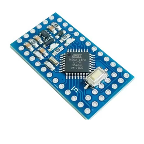
The Arduino Pro Mini board with the ATmega168PA chip running at 3.3V/8MHz is a compact, low-power option for embedded projects. This version has half the flash memory compared to the more common ATmega328P model.
Key Specifications
| Feature |
Detail |
| Microcontroller |
ATmega168PA |
| Operating Voltage |
3.3V |
| Clock Speed |
8 MHz |
| Flash Memory |
16 KB |
| SRAM |
1 KB (approx) |
| EEPROM |
512 bytes (approx) |
| Digital I/O Pins |
14 (6 PWM outputs) |
| Analog Input Pins |
8 (A0-A7) |
| Input Voltage (RAW) |
3.35V to 12V |
ATmega168PA vs. ATmega328P
The primary difference between boards with the ATmega168PA chip and those with the ATmega328P chip is the memory capacity.
- Flash Memory: The ATmega168PA has 16KB of flash memory, while the ATmega328P has 32KB. This limits the size and complexity of the programs (sketches) that can be uploaded to the 168PA-based board.
- SRAM/EEPROM: The ATmega168PA also has less SRAM and EEPROM compared to its counterpart.
For basic sensor and switch applications, the 16KB of flash memory is often sufficient, but for more complex projects, the ATmega328P version is recommended.
The Pro Mini is intended for advanced users who require a minimalist, permanent solution for their projects. Its small size, low power requirements, and 3.3V operation make it ideal for integration into various custom applications:
- Portable and Battery-Powered Devices: The 3.3V/8MHz configuration is highly energy-efficient, making it suitable for projects running on LiPo, coin cell, or multiple alkaline batteries.
- Wearables and Robotics: The compact form factor allows the board to be integrated into small, custom enclosures for wearables, drones, or small robotic systems.
- Wireless Sensor Networks: It is frequently used as a remote sensor node (e.g., in home automation or environmental monitoring systems) due to its ability to interface with various sensors and its low power consumption during data acquisition.
- Embedded Projects: Ideal for final products or semi-permanent installations where an external programmer is no longer needed after development.
- Prototyping: A versatile tool for experienced hobbyists and engineers for building custom electronic modules and prototypes.
Q: What is the main difference between the ATmega168PA and ATmega328P versions?
The primary difference is memory capacity. The ATmega168PA has 16KB of Flash memory, 1KB of SRAM, and 512 bytes of EEPROM. The ATmega328P has double the memory: 32KB Flash, 2KB SRAM, and 1KB EEPROM. Choose the 328P if your program requires more memory.
Q: Why does this board run at 8MHz instead of 16MHz?
The operating speed is tied to the operating voltage. Running the chip at 8MHz at 3.3V ensures stable and safe operation, whereas 16MHz requires 5V.
Q: Does this board have an on-board USB port?
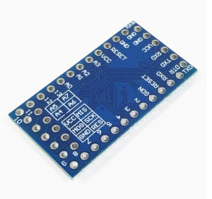
No, the Pro Mini does not have an on-board USB-to-serial converter to save space and cost. An external FTDI Basic Breakout board or FTDI cable is required for programming.
Q: How do I power the Pro Mini?
You have two main options:
- Regulated 3.3V Source: Connect a stable 3.3V source directly to the VCC pin.
- Unregulated Source (Batteries): Connect an unregulated power supply (between 3.35V and 12V, such as a 9V battery or a 2S LiPo) to the RAW pin. The on-board voltage regulator will step this down to a regulated 3.3V.
Q: Can I use 5V components with this 3.3V board?
This can be risky. The board operates on 3.3V logic. Connecting 5V signals directly to the input pins may damage the microcontroller. You must use a logic level shifter to safely interface between 3.3V and 5V components.
Q: How do I upload a program (sketch) to the Pro Mini?
- Connect your external FTDI adapter to the 6-pin programming header, ensuring the GRN and BLK pins align.
- In the Arduino IDE, go to Tools > Board and select
Arduino Pro or Pro Mini.
- Under Tools > Processor, select
ATmega168 (3.3V, 8 MHz).
- Select the correct COM port for your FTDI adapter.
- Press the upload button in the IDE.
Q: I'm getting an "avrdude: stk500_getsync()" error when uploading. What do I do?
This is a common communication error.
- Ensure the correct board and processor are selected in the IDE.
- Verify you have the correct FTDI drivers installed.
- Try a different USB cable, as faulty cables are a common problem.
- Press the physical reset button on the Pro Mini just as the Arduino IDE output switches to “Uploading…”.