Introduction to IO:bit
The IO:bit expansion board is a powerful microbit expansion board. It leads out 19 PIN pins of the microbit main board. Each PIN pin has VCC and GND corresponding to it. The VCC can be freely switched to 3V3 or 5V through the jumper cap. ;Contain 3 independent 3V3 and 5V pins, the wiring method is more flexible and diverse; In addition, the SDA and SCL pins of I2C, as well as the corresponding 5V and GND pins, are provided for the connection of modules such as LCD1602 liquid crystal display screen of I2C communication. Multiple possibilities; on-board passive buzzer, connected through jumper caps; power supply methods include DC head and USB socket power supply.
IO:bit parameter
PCB board thickness: 1.6mm
Small hole diameter: 3.0mm
Large round hole diameter: 4.6mm (compatible with Lego holes)
Product Size: 57mm/39mm/15mm
Net weight: 18.7g
USB input voltage: 5V
DC head input voltage: 6-12V
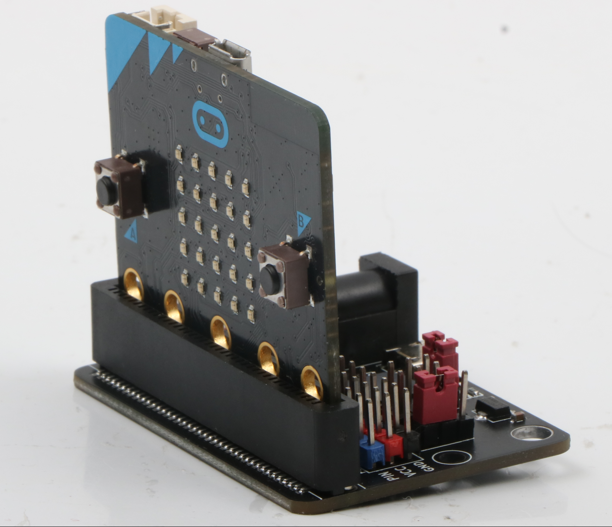
Product physical map
IO:bit expansion board and microbit motherboard

IO:bit pin introduction
IO:bit expansion board front function diagram

19 PIN pins

In the design process of IO:bit, it is fully considered that for developers who want to use the microbit pins deeply, all the IO ports of the microbit are drawn out, and each PIN pin has a corresponding label and a simple identification of the pin function. The blue lines of the pins represent IO pins, the red lines represent VCC, and the black lines represent GND. Among them, the passive buzzer is connected to the P0 pin through the jumper cap.
3V3, 5V pins

In the process of developing with microbit, if you use a module that requires 5V voltage, you can connect it to the 5V interface of the expansion board through a DuPont cable; if you need a 3V3 voltage module, you can connect it to the 3V3 interface of the expansion board through a DuPont cable.
Introduction of jumper caps

The IO:bit expansion board has two jumper caps. The first jumper cap is used to control the VCC voltage value of the IO pin in the expansion board. You can choose to connect 3V3 or 5V. The second jumper cap is used to control the board. For the passive buzzer, when the jumper cap pin is the Buzzer pin, the onboard passive buzzer is connected to the P0 pin of the microbit, and the corresponding music can be played through the microbit graphical music program building block.
I2C pins

The 19-way PIN pins of the IO:bit expansion board already include the P19 and P20 pins for I2C communication. In order to be more flexible and convenient to use, a complete I2C communication pin is specially designed for I2C communication. 4 pins, 5V pin, SCL pin, SDA pin, GND pin.
Power socket

The IO:bit expansion board has two power supply modes. During use, it can be powered by USB or the battery of the DC head. When the expansion board is powered on, the on-board red power indicator will light up.