Product Overview
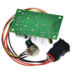
The CCM2 PWM DC Motor Speed Controller is a compact, feature-rich speed regulation module designed for brushed DC motors requiring both speed and direction control. With a wide input voltage range of 10V to 30V and a current capacity of 5A (120W maximum) , this controller provides smooth, stepless speed adjustment and convenient forward/reverse switching in a single, easy-to-use package .
Unlike basic speed controllers that only offer variable speed, the CCM2 incorporates a dedicated forward/reverse switch, allowing you to change motor direction instantly without swapping wires. This makes it an ideal solution for applications such as conveyor systems, automated gates, winches, robotics, and other bidirectional motion control tasks .
Utilizing advanced Pulse Width Modulation (PWM) technology, this controller delivers stepless speed adjustment from 0% to 100% duty cycle. The high-frequency PWM ensures smooth motor operation and maintains excellent torque even at low speeds. A built-in LED indicator provides clear visual confirmation when the controller is active, and a replaceable fuse offers reliable overload protection .
This controller is the ideal choice for a wide range of applications, including:
-
Industrial Automation: Conveyor belts, automated assembly lines, packaging equipment
-
Automated Gates & Barriers: Swing gates, sliding gates, parking barriers
-
Robotics: Robotic arms, mobile robots, turntables
-
Marine Applications: Trolling motors, winches, anchor lifts
-
Workshop Tools: Lathes, milling machines, drill presses (with direction change capability)
-
Electric Vehicles: Mobility scooters, golf carts (with forward/reverse functionality)
Key Features
-
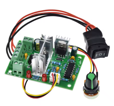
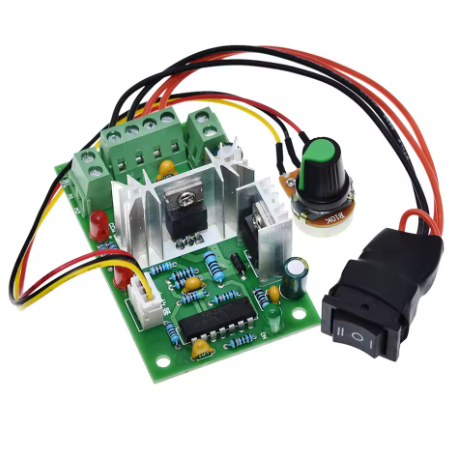
Bidirectional Speed Control: Features a dedicated forward/reverse toggle switch, allowing you to change motor direction instantly without rewiring. The controller includes a center-off position for safety and convenience.
-
Wide Voltage Compatibility: Accepts DC input from 10V to 30V, providing compatibility with 10V, 12V, 24V, and 30V systems, including standard battery packs and power supplies.
-
120W High Power Capacity: Rated for 5A continuous current with a maximum output power of 120W (at 24V), delivering reliable power for a wide range of medium-power DC motors.
-
Stepless Speed Adjustment: Features a high-quality rotary potentiometer for smooth, continuous speed control from 0% to 100% duty cycle, allowing precise adjustment to match your application requirements.
-
PWM Technology for Smooth Control: Utilizes high-frequency PWM to provide vibration-free speed adjustment with excellent torque retention even at low speeds.
-
Replaceable Fuse Protection: Includes a user-replaceable fuse holder (5x20mm) for reliable overload and short-circuit protection. Easily replace the fuse if a fault occurs—no soldering required.
-
LED Power Indicator: An onboard LED provides clear visual confirmation when power is applied and the controller is active, simplifying troubleshooting and operation monitoring.
-
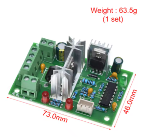
Compact and Lightweight: Small PCB footprint and low weight allow for easy integration into tight spaces and portable applications.
-
Easy Wiring: Clearly labeled screw terminals for power input (V+/V-), motor output (M+/M-), and an integrated forward/reverse switch for intuitive control.
Technical Specifications
Pinout & Interface Guide
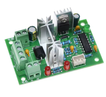
The controller features clearly labeled screw terminals and integrated controls.
Power Terminals
-
V+ / VIN+ (Power Input +): Connect the positive terminal of your DC power source (10V-30V) here. Observe correct polarity (+ to +, – to -).
-
V- / VIN- (Power Input -): Connect the negative terminal (ground) of your DC power source here.
Motor Terminals
Note: The motor wires are non-polarized. If the motor runs forward when the switch is set to reverse, swap the two wires at the M+ and M- terminals to correct the orientation.
Control Interface
Safety Note: The center-off position allows you to stop the motor without changing the speed setting, providing convenient on/off control.
Status Indicators
Fuse Holder
Usage Guide
Important Safety Warnings
-
DC ONLY: This controller is designed strictly for DC circuits. Never connect it to AC mains power (e.g., 110V or 220V AC). Doing so will instantly destroy the controller and poses a serious fire hazard.
-
Polarity Matters: Do not reverse the positive and negative terminals of the DC power supply. This will damage the controller.
-
Motor Type: This controller is for brushed DC motors only. It is NOT compatible with brushless DC motors (BLDC), stepper motors, or AC motors.
-
Current Limits: The controller is rated for 5A continuous current. Prolonged operation at currents exceeding 5A may cause overheating or fuse failure.
-
Proper Wiring: Use appropriately sized wire for 5A operation (minimum 18 AWG recommended) to minimize voltage drop and heating.
-
Direction Switching: Avoid switching direction while the motor is spinning at high speed, as this can cause high current spikes and potential damage. Allow the motor to stop (or use the center-off position) before changing direction.
Wiring Guide
Step-by-Step Operation
-
Mount the Controller: Secure the module in your enclosure using mounting tape or standoffs.
-
Connect the Motor: Connect your brushed DC motor to the M+ and M- terminals.
-
Connect the Power Supply: Connect your DC power source (10V-30V) to the V+ and V- terminals. Ensure the power supply is turned OFF or disconnected during wiring.
-
Set Initial Speed: Turn the speed control knob fully counter-clockwise to its minimum speed position.
-
Set Direction Switch: Ensure the forward/reverse switch is in the center (Off) position.
-
Apply Power: Turn on your DC power source. The power LED should illuminate.
-
Select Direction: Move the toggle switch to the Forward or Reverse position.
-
Adjust Speed: Slowly turn the speed control knob clockwise. The motor will begin to spin and increase in speed as you turn.
-
Stop the Motor: To stop, either turn the speed knob fully counter-clockwise or move the direction switch to the center (Off) position.
-
Change Direction: To reverse direction, first stop the motor (using either method), then move the switch to the opposite direction, and adjust speed as needed.
Motor Direction Calibration
If the motor rotates forward when the switch is set to reverse (or vice versa):
-
Turn off power.
-
Swap the two motor wires at the M+ and M- terminals.
-
Reapply power. The direction switch will now operate as labeled.
Q: What types of motors can I use with the CCM2 controller?
This controller is designed for brushed DC motors only operating at 10V to 30V, with a maximum current draw of 5A. It is ideal for motors found in conveyor belts, automated gates, winches, and small electric vehicles. It is not compatible with brushless DC motors (BLDC), stepper motors, or AC motors.
Q: What is the real-world current and power limit?
The controller is rated for 5A continuous current. The maximum power depends on your input voltage:
-
At 12V: Up to 60W (12V × 5A)
-
At 24V: Up to 120W (24V × 5A)
-
At 30V: Up to 150W (30V × 5A)
For sustained operation, it is recommended to stay within the 5A continuous rating.
Q: Does this controller have forward/reverse functionality?
Yes. The CCM2 features a dedicated forward/reverse toggle switch with a center-off position. This allows you to change motor direction instantly without rewiring, and the center-off position provides a convenient way to stop the motor while preserving your speed setting.
Q: Can I use this controller with a 24V battery system?
Yes. The controller accepts any DC voltage from 10V to 30V, making it compatible with 12V, 24V, and 30V systems. Always ensure your motor is rated for the voltage you apply.
Q: Can I use this controller to change direction while the motor is running?
It is not recommended to switch direction while the motor is spinning at high speed. Doing so can cause high current spikes that may trip the fuse or damage the controller. Always stop the motor (using the center-off position or reducing speed to zero) before changing direction.
Q: What power supply should I use?
Use a DC power source with a voltage between 10V and 30V that matches your motor’s rated voltage. The power source must be capable of delivering at least the current your motor will draw (up to 5A). Examples include:
Q: The controller gets warm. Is this normal?
Some warmth is normal when switching currents near 5A. The controller is designed to dissipate heat through its components and PCB. However, if it becomes too hot to touch, you may be exceeding the recommended continuous current rating. Ensure adequate ventilation and check that your motor is not drawing excessive current due to mechanical binding or stalling.
Q: What is the advantage of the center-off switch?
The center-off position provides several benefits:
-
Convenient stopping: Stop the motor without changing your speed setting
-
Safety: Prevents accidental startup during wiring or maintenance
-
Direction change safety: Allows you to stop the motor before reversing direction
Q: Does the speed knob have an off position?
The speed knob does not have an integrated switch. The center-off position of the direction switch is used to stop the motor while preserving your speed setting. To completely stop the motor, move the direction switch to the center position.
Q: The controller doesn't work. The motor doesn't move.
Follow this checklist:
-
Check Direction Switch: Ensure the switch is not in the center (Off) position.
-
Check Speed Knob: Ensure the knob is turned clockwise past the minimum speed position.
-
Check Fuse: If the controller recently stopped working, check the replaceable fuse. If the fuse is blown, replace it with a 5x20mm fuse of the same rating (check your specific module for the correct value, typically 5A or 10A).
-
Check Power: Verify with a multimeter that you have the correct DC voltage at the V+ and V- terminals (10V-30V).
-
Check Polarity: Ensure your power supply is connected with the correct polarity (+ to V+, – to V-).
-
Test the Motor: Connect your motor directly to the power source (briefly) to ensure it works.
Q: The motor runs in the wrong direction when I select forward.
This is easily fixed. Turn off the power, swap the two motor wires at the M+ and M- terminals, and then reapply power. The direction switch will now operate as labeled.
Q: The fuse keeps blowing. What's wrong?
Repeated fuse failure indicates an overload condition. Possible causes:
-
Your motor is drawing more than 5A continuously (check motor specifications)
-
Mechanical binding or stall condition causing excessive current draw
-
Short circuit in the motor wiring or motor itself
-
Switching direction while the motor is spinning at high speed
Solution: Ensure your motor’s continuous current draw is within 5A. Check for mechanical issues. Allow the motor to stop before changing direction. If the problem persists, consider a higher-rated controller for your application.
Q: Can I use this controller to dim LEDs?
While technically possible, this controller is optimized for inductive loads like motors. For LED dimming, a dedicated LED driver is recommended. The forward/reverse functionality would not be applicable for LED applications.
Q: Is there any reverse polarity protection?
This controller does not typically include reverse polarity protection. Always double-check your connections before applying power. Reversing the input polarity can instantly damage the controller.
Q: What size fuse should I use for replacement?
Consult the label on your specific CCM2 module. Typical fuse ratings are 5A or 10A, using a standard 5x20mm fast-blow ceramic fuse. Using a higher-rated fuse will compromise protection and may damage the controller.