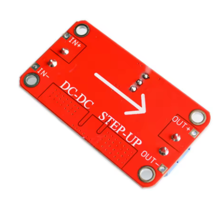
Description
The XL6019 5A Adjustable Boost Converter Module is a high-power, high-performance DC-DC step-up switching regulator designed for demanding applications requiring significant voltage boosting capability. As the natural upgrade to the popular XL6009 and the legacy LM2577, the XL6019 delivers superior power handling with a 5A switching current capacity, making it ideal for industrial equipment, automotive systems, LED lighting arrays, and high-power portable electronics .
At the heart of this module is the XL6019E1 chip from XLSEMI – a second-generation high-frequency switching regulator that integrates a powerful 5A N-channel MOSFET switch . The XL6019 supports a wide input voltage range from 5V to 40V and can generate adjustable output voltages from 5V up to 35V (or higher, depending on the module version) .
Key Technical Advantages:
Superior Design & Protection Features:
The XL6019 is not just a higher-current version of the XL6009 – it is a fundamentally more versatile chip. Unlike the XL6009 which is limited to boost (step-up) operation, the XL6019 can be configured as a boost, buck-boost, or inverting converter . This flexibility allows it to handle applications where the input voltage may fluctuate above or below the desired output voltage – perfect for automotive and battery-powered systems.
Built-in protection features include :
-
Soft-start function – Reduces inrush current at power-up
-
Over-voltage protection on the switch pin
-
Current limit and thermal shutdown – Protects the chip and load
-
Enable pin (EN) – TTL-compatible shutdown for remote power control
Wide Application Range:
-
Automotive Systems: Stabilizes 12V output from fluctuating vehicle electrical systems (9V-30V input)
-
Industrial Equipment: Boosts 12V to 24V for sensors, actuators, and PLCs
-
LED Lighting: Drives high-power 24V or 36V LED arrays
-
Battery-Powered Devices: Converts single Li-Ion cells (3.7V) to 5V, 9V, or 12V
-
Solar Power Systems: Regulates variable solar panel output to stable voltages
Important Operating Note: While the XL6019 chip is capable of buck-boost operation, many ready-made modules are configured as boost (step-up) converters only. Check your specific module’s documentation to confirm its configuration.
Whether you are an electronics hobbyist working on high-power projects, an IoT developer needing robust voltage conversion, or an industrial engineer designing power systems, the XL6019 5A Boost Converter Module provides the power, efficiency, and reliability you need.
Key Features
-
5A Peak Switching Current – High-power 5A internal MOSFET handles demanding loads, significantly outperforming XL6009 (4A) and LM2577 (3A)
-
Wide Input Voltage Range – Accepts DC 5V to 40V input (some modules support as low as 3V), compatible with USB (5V), Li-Ion batteries, car systems (12V-14.5V), and industrial supplies
-
Adjustable Output Voltage – Output can be set from 5V up to 35V (some versions up to 40V-45V) via onboard multi-turn potentiometer
-
High Conversion Efficiency – Up to 94% efficiency minimizes power loss and heat generation, even at high power levels
-
Multiple Topology Support – XL6019 chip can be configured for Boost, Buck-Boost, or Inverting operation (check your specific module)
-
Enable Pin Control – Built-in EN pin for remote on/off control using logic-level signals (TTL compatible)
-
Comprehensive Protection – Features soft-start, over-voltage protection, current limiting, and thermal shutdown for reliable operation
-
220kHz Switching Frequency – Fixed frequency operation provides predictable performance and easier filtering
-
Screw Terminal Connections – Easy, solderless wiring for input and output connections
-
Wide Operating Temperature – -40°C to +85°C for reliable operation in automotive, industrial, and outdoor environments
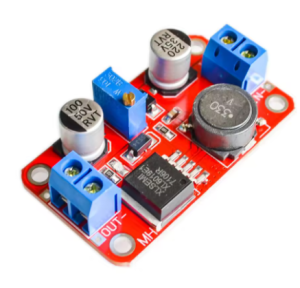
Technical Parameters
Usage Guide
Pinout Description
The module features screw terminal blocks for easy connections:
Note: Input and output grounds are common (connected together on the board).
Wiring Instructions
Step 1 – Connect Input Power
Step 2 – Connect Load
Step 3 – (Optional) Connect Enable Pin for Remote Control
-
For always-on operation, leave EN pin disconnected (floating – default HIGH)
-
For remote control, connect EN to a microcontroller GPIO pin (3.3V or 5V logic compatible)
Step 4 – Power On and Adjust
Adjusting the Output Voltage
⚠️ CRITICAL: The “Endless Turn” Issue
This is the most common point of confusion. The potentiometer often ships at its maximum resistance position. If you turn the screw and see no voltage change, you need to turn it counter-clockwise for 10-15 full rotations before the voltage begins to increase. Keep turning while watching your multimeter until the voltage starts to rise. The potentiometer is multi-turn, so you won’t damage it.
Proper Adjustment Procedure:
-
Power the module using your input source (5V-40V DC)
-
Connect a multimeter to the OUT+ and OUT- terminals
-
Use a small screwdriver to turn the blue potentiometer:
-
Monitor the multimeter while adjusting
-
Adjust before connecting load – It is recommended to set output voltage with no load connected
Typical Voltage Settings by Application:
Understanding the XL6019’s Versatility
Unlike the XL6009 which is limited to boost (step-up) operation, the XL6019 chip can be configured in multiple topologies :
⚠️ Important: Most ready-made modules are configured as boost converters only. Check your specific module’s documentation to confirm its configuration. If you need buck-boost capability, verify before purchasing.
Power Ratings and Thermal Management
The XL6019 chip has a 5A switching current limit, but practical output current depends on several factors:
Recommended Output Current Guidelines:
Power Calculation Examples:
Important Current Relationship: Boost converters draw more input current than output current due to power conservation:
Power In × Efficiency = Power Out or VIN × IIN × Efficiency = VOUT × IOUT
Example: To get 1.5A at 24V output (36W) from a 12V input, the input current must be approximately 3.2A-3.5A (accounting for efficiency losses). Ensure your input power source can supply sufficient current.
Heat Management Tips:
-
Add a heatsink to the XL6019 chip for continuous loads above 1.5A
-
Ensure adequate airflow around the module
-
Consider using a higher input voltage to reduce the voltage conversion ratio and associated heat
-
The module includes thermal shutdown protection, but good thermal design is still recommended
Important Operating Restrictions
Voltage Limitation (Critical):
This module is configured as a step-up (boost) converter only in most ready-made versions. If your module is a standard boost converter, the output voltage must always be set higher than the input voltage. If the input voltage exceeds the set output voltage, the module will not regulate down, and the output will approximately follow the input voltage, potentially damaging your load.
For buck-boost versions: The output voltage can be higher or lower than the input, making them ideal for automotive applications where input voltage fluctuates (e.g., 9V-30V input to stable 12V output) .
Reverse Polarity Warning:
Most modules do NOT have reverse polarity protection. Double-check your IN+ and IN- connections before applying power. Connecting backwards will instantly destroy the module.
Short Circuit Protection:
The XL6019 chip includes over-current limiting, but this is not a full short circuit protection feature. Adding a small fuse on the input line is good safety practice.
Using the Enable Pin (If Available)
Some XL6019 modules expose the EN pin for remote control :
Connecting to a Microcontroller (Arduino Example):
const int ENABLE_PIN = 7;
void setup() {
pinMode(ENABLE_PIN, OUTPUT);
digitalWrite(ENABLE_PIN, HIGH);
}
void loop() {
digitalWrite(ENABLE_PIN, HIGH);
delay(10000);
digitalWrite(ENABLE_PIN, LOW);
delay(5000);
}
Example Applications
Installation Tips
-
Polarity Check: Always double-check input polarity before applying power
-
Initial Setup: Adjust output voltage with no load connected first
-
Enable Pin: Leave floating for always-on operation; connect to control signal for remote management
-
Keep Wires Short: Long wires add resistance and inductance, reducing efficiency
-
Use a Fuse: Add a fuse (e.g., 5A) on the input line as safety protection
-
Heat Sinking: For loads >1.5A continuous, attach a heatsink to the XL6019 chip
-
Start with Low Load: When first testing, use a low-current load to verify voltage setting before connecting sensitive equipment
Q: What is the difference between XL6019 and XL6009?
The XL6019 is a higher-power and more versatile upgrade to the XL6009:
For high-power applications or projects requiring voltage regulation where input may fluctuate above and below output (e.g., automotive), XL6019 is the superior choice
Q: Can this module step down voltage as well as step up?
It depends on the specific module. The XL6019 chip itself supports buck-boost (step-up and step-down) operation . However, many ready-made modules are configured as boost converters only. Check your module’s documentation – if it’s a buck-boost version, it can maintain a stable output even when input voltage varies above and below the set output
Q: What is the maximum output current?
The chip has a 5A switching current limit . Practical output current depends on input/output voltages, cooling, and efficiency:
-
1.5A – 2A: Safe for continuous operation without heatsink
-
2A – 2.5A: Possible with heatsink and good airflow
-
3A+: Peak/short duration only
User reviews confirm that 5A is the switch limit, not the continuous output rating – treat as 2-3A maximum for reliable operation
Q: Why is my output voltage not changing when I turn the potentiometer?
This is the most common issue. The potentiometer typically needs to be turned counter-clockwise for 10-15 full rotations before the voltage begins to change. Keep turning while watching your multimeter until the voltage starts to rise. The potentiometer is multi-turn, so you won’t damage it.
Q: Does this module have short circuit or reverse polarity protection?
The XL6019 chip includes over-current limiting and thermal shutdown, but these are not full short circuit protection features . Reverse polarity protection is NOT included – double-check your connections before applying power. Adding a fuse on the input line is recommended for safety.
Q: Can I use this module in a car (12V-14.5V electrical system)?
Yes, but choose the right version. If your car’s electrical system fluctuates (typically 9V-30V in vehicles), use a buck-boost version of the XL6019 module to maintain a stable output regardless of input variations . A standard boost-only version cannot step down when voltage spikes above your set output.
Q: Why is my module getting very hot?
Heat is normal in boost converters, especially when:
-
Drawing high current (>1.5A continuous)
-
Boosting a low voltage to a much higher voltage
-
Operating without adequate airflow
Solutions: Add a heatsink, reduce load current, use a higher input voltage (to reduce conversion ratio), or improve ventilation. The XL6019 includes thermal shutdown protection, but good thermal design is still essential
Q: Can I use this module for both home and business applications?
Home users: High-power LED lighting, DIY power stations, battery charging systems, 12V to 24V conversion for tools, portable speaker power supplies.
Business users: Industrial equipment power supplies, automotive voltage stabilization, solar/wind power conditioning, LED lighting systems, prototype development, remote sensor networks, PLC power supplies.
Q: What is the efficiency of this module?
The XL6019 achieves up to 94% efficiency under optimal conditions (moderate load, small input-output voltage difference) . Efficiency drops with very large voltage differences or very light/heavy loads. User testing reports approximately 80% efficiency at higher power levels (12V to 24V at 1.5A)
Q: What is included in the package?
(Heatsink not included; some kits may include connecting wires)