Product Overview
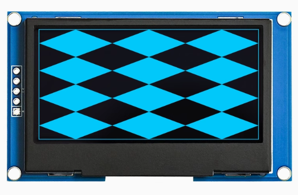
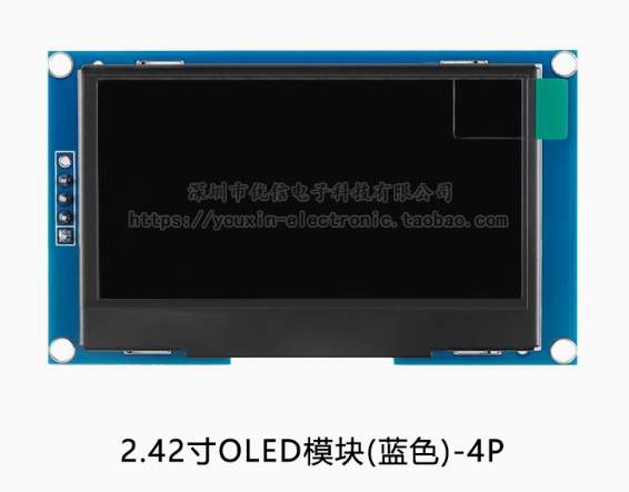
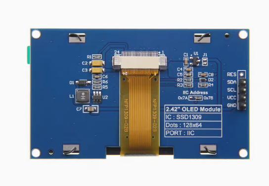
The 2.42-inch Passive Matrix OLED Display Module is a large-format, high-contrast monochrome graphic display designed for embedded systems, industrial control panels, medical equipment, and IoT devices. Powered by the SSD1309 driver IC and featuring a crisp 128×64 pixel resolution, this display delivers bright blue text, detailed graphics, and custom icons on a true black background — all in a spacious 2.42-inch diagonal format.
Why the SSD1309 Controller? Unlike the common SSD1306 controller used on smaller OLEDs, the SSD1309 is specifically designed for larger OLED panels. Key advantages include:
-
Higher row drive current for brighter, more uniform illumination across the larger screen area
-
External boost regulator to generate the higher voltage needed for 2.42″ panels
-
Command compatibility with SSD1306, making library migration simple
The 5-pin I2C interface (GND, VCC, SCL, SDA, RES) requires only two data lines to connect to your microcontroller, preserving valuable I/O pins for other peripherals. A dedicated RES (reset) pin allows hardware initialization for reliable startup.
This module works with 3.3V logic systems (ESP32, ESP8266, STM32, Raspberry Pi). The I2C lines are 5V tolerant, making it safe for direct connection to 5V Arduino boards — provided VCC is supplied with 3.3V.
Key Features
-
Large 2.42-Inch Active Area: 55.01 × 27.49mm display area — approximately 6 times larger than 0.96″ OLEDs, providing significantly more screen real estate for dashboards, data visualization, and UI elements
-
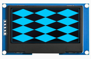
Blue Monochrome OLED: Bright blue pixels on true black background provide exceptional contrast (10,000:1) and a distinctive, modern appearance
-
SSD1309 Driver IC: Advanced controller specifically designed for larger OLED panels, featuring 128 × 64-bit SRAM buffer and 256-step contrast control
-
5-Pin I2C Interface: Pins GND, VCC, SCL, SDA, RES — requires only 2 data lines with default address 0x3C, saving GPIO pins
-
Dedicated RESET Pin: Hardware reset control for reliable display initialization; requires 10kΩ pull-up to VCC
-
Wide Operating Temperature: Rated for -40°C to +85°C, suitable for industrial, outdoor, and automotive applications
-
Full Viewing Angle: >160° visibility ensures clear readouts from any angle without contrast shift
-
Ultra-Thin COG Construction: Chip-on-Glass design with 2.15mm thickness, ideal for portable devices and space-constrained installations
-
Low Power Consumption: Only lit pixels consume power — ideal for battery-powered projects
Technical Specifications
Pinout & Connection Guide
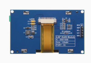
The module features a 5-pin I2C interface. Pin order may vary between manufacturers — always verify the silkscreen on your specific module.
Pin Definitions (5-Pin)
⚠️ Critical Wiring Notes
-
VCC must be 3.3V only — do not connect to 5V
-
RES pin requires a 10kΩ pull-up to VCC for reliable operation
-
The I2C lines (SDA/SCL) are 5V tolerant, so direct connection to 5V Arduino is safe for the I2C signals — but VCC must still be 3.3V
RESET Pin Configuration
The RES pin is critical for reliable operation. The module requires a proper reset signal to initialize correctly:
-
Recommended: Connect RES to a microcontroller GPIO pin with a 10kΩ pull-up resistor to VCC
-
The GPIO should drive the pin HIGH during normal operation
-
Some modules may require the RES pin to be toggled (HIGH → LOW → HIGH) during initialization
I2C Address Configuration
The I2C address is determined by the DC pin state (configured via PCB resistors):
For this blue module, the default configuration is typically 0x3C.
Wiring Examples
Wiring to ESP32 (3.3V — Recommended)
Wiring to Arduino Uno (5V — I2C lines only)
⚠️ VCC must be 3.3V — do not use the Arduino’s 5V pin
Wiring to Raspberry Pi
Usage Guide
Power Supply Considerations
The 2.42″ OLED draws more current than smaller OLEDs due to its larger active area. Typical current draw is around 20-80mA depending on the number of pixels lit. Ensure your 3.3V power source can deliver adequate current. The Arduino Uno’s onboard 3.3V regulator is limited; for reliable operation, use an external 3.3V regulator.
Software Setup (Arduino IDE)
Step 1: Install Required Libraries
The U8g2 library by Oliver Kraus is the most reliable for SSD1309 displays, offering excellent support and many font options.
-
Open Arduino IDE → Sketch → Include Library → Manage Libraries
-
Search for “U8g2” by Oliver Kraus
-
Click Install
Step 2: I2C Address Verification
Run this I2C scanner to verify your display’s address before using it:
#include <Wire.h>

void setup() {
  Wire.begin();
  Serial.begin(9600);
  Serial.println("I2C Scanner");
}

void loop() {
  byte error, address;
  int nDevices = 0;

  for(address = 1; address < 127; address++) {
    Wire.beginTransmission(address);
    error = Wire.endTransmission();

    if(error == 0) {
      Serial.print("I2C device found at address 0x");
      if(address < 16) Serial.print("0");
      Serial.println(address, HEX);
      nDevices++;
    }
  }

  if(nDevices == 0) Serial.println("No I2C devices found");
  delay(5000);
}
The display should appear at address 0x3C.
Step 3: Basic Test Sketch (U8g2 Library)
This example uses the correct constructor for the 2.42″ SSD1309 display:
#include <Arduino.h>
#include <U8g2lib.h>
#include <Wire.h>
U8G2_SSD1309_128X64_NONAME0_F_HW_I2C u8g2(U8G2_R0, 4);
void setup() {
pinMode(4, OUTPUT);
digitalWrite(4, HIGH);
u8g2.begin();
u8g2.enableUTF8Print();
u8g2.setFont(u8g2_font_ncenB08_tr);
}
void loop() {
u8g2.firstPage();
do {
u8g2.drawStr(0, 15, "2.42 OLED");
u8g2.drawStr(0, 35, "128x64");
u8g2.drawStr(0, 55, "SSD1309 - I2C");
u8g2.drawStr(0, 75, "Blue Display");
} while ( u8g2.nextPage() );
delay(1000);
}
Step 4: Setting I2C Address (If Needed)
If your display responds to address 0x3D instead of 0x3C, adjust the address in code:
u8g2.setI2CAddress(0x7A);
Alternative: Adafruit Library
The Adafruit_SSD1306 library is command-compatible with SSD1309:
#include <Wire.h>
#include <Adafruit_GFX.h>
#include <Adafruit_SSD1306.h>
#define SCREEN_WIDTH 128
#define SCREEN_HEIGHT 64
#define OLED_RESET 4
Adafruit_SSD1306 display(SCREEN_WIDTH, SCREEN_HEIGHT, &Wire, OLED_RESET);
void setup() {
display.begin(SSD1306_SWITCHCAPVCC, 0x3C);
display.clearDisplay();
display.setTextSize(1);
display.setTextColor(SSD1306_WHITE);
display.setCursor(0, 0);
display.println("2.42 OLED");
display.println("SSD1309 Ready!");
display.display();
}
Raspberry Pi Setup (Python)
-
Enable I2C: sudo raspi-config → Interface Options → I2C → Yes → Reboot
-
Install required libraries:
sudo apt-get install python3-pip
pip3 install luma.oled
-
Python example code:
from luma.core.interface.serial import i2c
from luma.oled.device import ssd1309
from luma.core.render import canvas
serial = i2c(port=1, address=0x3C, gpio_RST=17)
device = ssd1309(serial, width=128, height=64)
with canvas(device) as draw:
draw.rectangle(device.bounding_box, outline="white", fill="black")
draw.text((10, 25), "2.42 OLED", fill="white")
draw.text((10, 45), "128x64 Ready!", fill="white")
Q: What is the difference between SSD1309 and SSD1306?
The SSD1309 is designed specifically for larger OLED panels (2.42″ and up). Key differences include: higher row drive current for brighter, more uniform illumination; external boost regulator instead of internal charge pump; and command compatibility with SSD1306, making library migration straightforward.
Q: Can I use this display with a 5V Arduino Uno?
Yes, but with important caveats. The I2C lines (SDA/SCL) are 5V tolerant and can be connected directly to 5V pins. However, the VCC pin must be powered with 3.3V — do not apply 5V to VCC. The Arduino Uno’s onboard 3.3V regulator may not supply enough current; use an external 3.3V regulator.
Q: What is the default I2C address?
The default I2C address is 0x3C (7-bit), corresponding to 0x78 (8-bit write address). Some modules can be configured to 0x3D (0x7A) via the DC pin state. Run an I2C scanner to verify your specific module’s address.
Q: Why does my display stay blank after power-up?
The display requires a proper reset signal to initialize. Connect the RES pin to a microcontroller GPIO and pull it HIGH to VCC through a 10kΩ resistor. Some modules require the RES pin to be toggled (HIGH → LOW → HIGH) during setup for reliable initialization.
Q: What is the RES pin for and do I need to use it?
The RES pin is used to reset the display driver — it is strongly recommended for reliable operation. The simplest approach is to connect it to a GPIO with a 10kΩ pull-up to VCC and drive it HIGH in your setup code. Do not leave it floating.
Q: How do I use the RES (reset) pin correctly?
The RES pin is active low — pulling it LOW resets the display. For normal operation, it should be pulled HIGH. Connect it to a microcontroller GPIO with a 10kΩ pull-up resistor to VCC (3.3V). In your setup code, set the pin HIGH.
Q: Does this blue display have visible pixel grid lines?
The 2.42″ OLED has a pixel pitch of 0.43mm, which may make individual pixels slightly visible at close viewing distances. This is normal for larger OLED displays and contributes to the classic “digital” appearance.
Q: Can I use this display with MicroPython?
Yes. The SSD1309 is supported via SSD1306-compatible drivers. For ESP32, use the ssd1306 module with I2C interface:
from machine import Pin, I2C
import ssd1306

i2c = I2C(0, scl=Pin(22), sda=Pin(21), freq=400000)
oled = ssd1306.SSD1306_I2C(128, 64, i2c, addr=0x3C)
Q: What libraries are recommended for this display?
The U8g2 library by Oliver Kraus is the most reliable for SSD1309 displays, offering extensive font support and proper handling of the SSD1309 controller. The Adafruit_SSD1306 library is also command-compatible and works well.
Q: How do I display Chinese characters or custom fonts?
The U8g2 library supports UTF-8 encoding. Enable with u8g2.enableUTF8Print() and use fonts like u8g2_font_wqy12_t for Chinese characters. For custom fonts, use tools like LCD Image Converter to convert text into bitmap data arrays.