Product Overview
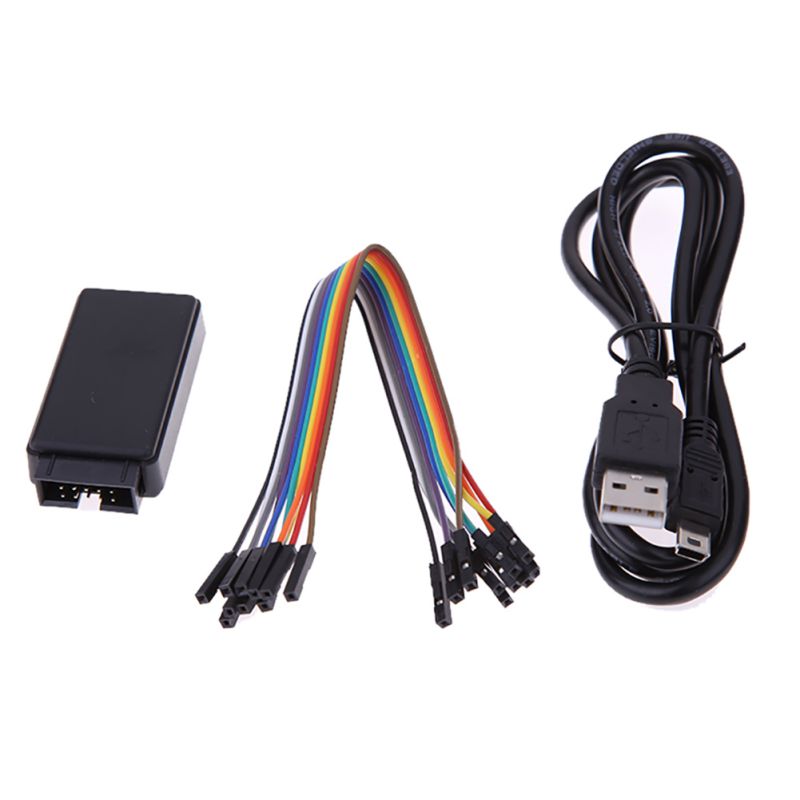
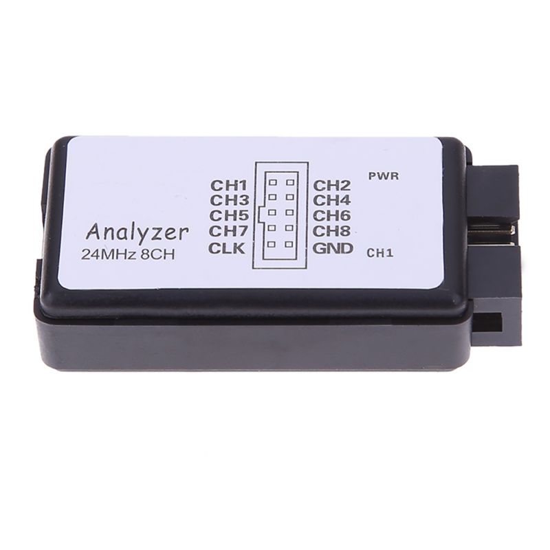
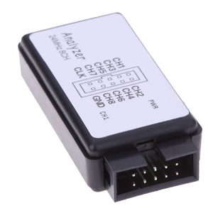
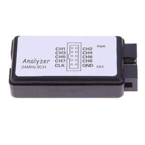
The 8-Channel 24MHz USB Logic Analyzer is a compact, high-performance debugging tool designed to capture and analyze digital signals in real-time. Whether you are troubleshooting a malfunctioning I2C sensor, reverse-engineering an unknown communication protocol, or verifying timing constraints on an FPGA, this device is an indispensable tool for any hardware developer’s workbench.
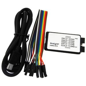
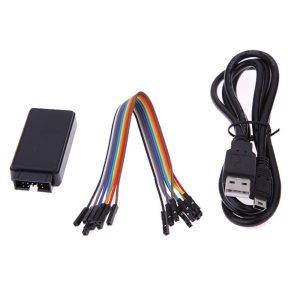
Unlike bulky oscilloscopes, this logic analyzer focuses purely on the logic state (HIGH/LOW) of digital signals over time. With support for sampling rates up to 24MHz and 8 simultaneous channels, it can accurately capture the intricate details of serial protocols like SPI, UART, and I2C. It connects to your computer via USB (with many modern versions featuring a USB Type-C interface) and is powered directly from the bus—no external power supply is needed.
The device is fully compatible with the open-source Sigrok/PulseView software suite. This powerful software provides protocol decoding for over 100 protocols, allowing you to translate raw waveforms into readable data packets instantly. Supporting Windows, Linux, macOS, and even Android, this tool is a favorite among electronics enthusiasts, embedded engineers, and professional developers.
Key Features
-
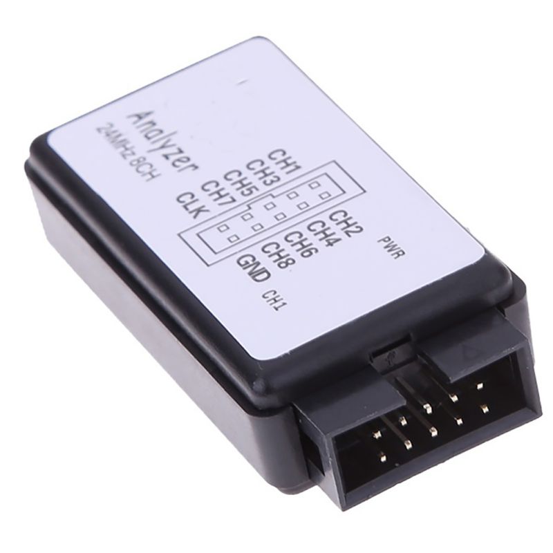
8 Logic Channels: Monitor up to eight digital signals simultaneously, perfect for analyzing data buses like SPI (4 lines) or UART (TX/RX) while monitoring other GPIOs.
-
24MHz Sampling Rate: Capture high-speed signal transitions with ease. Adjustable sampling rates down to 20kHz allow for capturing both high-speed bursts and long-duration low-speed signals.
-
Wide Logic Compatibility: Works with 3.3V and 5V systems. The input voltage range is typically -0.5V to 5.25V (High threshold: >2.0V), making it safe for standard microcontrollers and FPGAs.
-
Open-Source Software Support: Fully compatible with Sigrok / PulseView, a free, open-source, cross-platform software suite. Also compatible with Saleae Logic software (for 8-channel models) on some clones.
-
Extensive Protocol Decoding: Decode over 100 protocols out-of-the-box, including UART, I2C, SPI, 1-Wire, CAN, and I2S. You can even add custom protocols.
-
High Input Impedance: Input impedance >100kΩ, 5pF ensures minimal loading on the circuit you are testing.
-
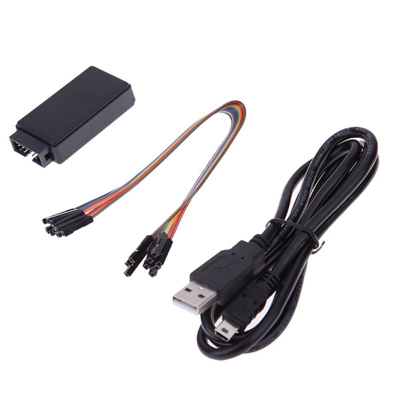
Plug-and-Play: Powered entirely by the USB connection. Simply plug it in and start capturing.
-
Modern USB Interface: Features a durable USB Type-C connector for reliable connectivity.
Technical Specifications
Usage Guide
1. Software Installation (PulseView)
To use the logic analyzer, you need to install the PulseView software and the necessary USB drivers.
-
Download: Go to the official Sigrok website or a trusted supplier’s datasheet link to download the PulseView installer for your OS (Windows, macOS, Linux).
-
Install: Run the installer and follow the on-screen instructions.
2. Driver Installation (Windows)
Before connecting the device, you need to install the driver using Zadig so the software can recognize the hardware.
-
Connect: Plug the Logic Analyzer into your computer’s USB port.
-
Open Zadig: Locate zadig.exe in the PulseView installation directory (usually C:\Program Files (x86)\sigrok\PulseView).
-
Select Device: From the Options menu, select List All Devices. Choose the device named “fx2lafw” from the dropdown list (USB ID usually 1D50:608C).
-
Install Driver: Select WinUSB as the driver in the target box and click “Install Driver”.
Once successfully installed, the device should appear as a recognized “USB Serial Device” in Device Manager under “Universal Serial Bus Devices”.
3. Connecting to Your Device
-
Ground: Connect one of the analyzer’s GND pins to the Ground (GND) of your target device. This establishes a common reference voltage.
-
Channels: Connect the analyzer’s channels (e.g., CH0, CH1) to the test points or pins you wish to monitor.
-
Power: The device is powered solely by the USB connection to your PC.
4. Capturing Data with PulseView
-
Launch: Open the PulseView application.
-
Device Scan: Click the “Scan for devices” button on the toolbar. Ensure the “fx2lafw” device is detected.
-
Configure Capture:
-
Sample Rate: Set the sample rate (e.g., 1MHz or 24MHz). Higher rates capture finer details but fill the buffer faster.
-
Number of Samples: Set the number of samples to capture, just like setting the time base on an oscilloscope.
-
Channel Selection: Enable only the channels you are using to optimize buffer capacity.
-
Run: Click the “Run” button to start the acquisition. Trigger on a rising/falling edge or simply let it run.
-
Analyze: Zoom and pan through the waveform. Use the decoder function on the right sidebar to select protocols like I2C or UART to convert the logic levels into readable text.
Q: Is this logic analyzer compatible with 5V systems (like Arduino Uno)?
Yes, absolutely. The device is designed to accept logic levels up to 5.25V, with a logic-high threshold of 2.0V. It is perfectly safe for use with 5V Arduino boards, 3.3V ESP32s, and 1.8V systems, provided the voltage does not exceed the 5.25V absolute maximum.
Q: Can I use this to debug Raspberry Pi GPIO?
Yes. You can use it to monitor the logic levels on the Raspberry Pi’s GPIO pins (3.3V logic). Connect the ground of the analyzer to a ground pin on the Pi, and connect a channel to the specific GPIO you want to monitor. Set the sample rate appropriately to capture the signal timing.
Q: What is the difference between a logic analyzer and an oscilloscope?
A logic analyzer digitizes logic states (HIGH/LOW) and is best for understanding bus communication (UART, I2C, SPI, timing relationships). An oscilloscope shows the analog voltage shape of a signal and is best for checking signal integrity (ringing, noise, rise times). Neither replaces the other; they are complementary tools. This device is a logic analyzer and cannot measure analog voltages.
Q: What software do I need to use this device?
This device is designed to work with the free and open-source Sigrok / PulseView software. Some versions may also be compatible with the Saleae Logic software, though open-source software like PulseView is recommended for the best compatibility and features.
Q: Why can't I install the driver on Windows 10/11?
This is usually because Windows is trying to assign a generic driver. You must use the Zadig tool. Ensure your device is listed as “fx2lafw” in Device Manager before attempting the driver swap. Also, make sure to run Zadig as Administrator.
Q: How accurate is the timing measurement?
The timing accuracy is determined by the sampling rate. At the maximum rate of 24MHz, the timing resolution is approximately 41.6ns (1/24MHz). This is sufficient for most microcontroller and serial communication debugging tasks.
Q: What does the sample rate mean, and what should I set it to?
The sample rate is how many times per second the analyzer checks the voltage on the pin (takes a picture). According to the Nyquist theorem, to accurately see a signal, you need to sample it at least twice as fast as the signal frequency. Rule of Thumb: For a 115200 baud UART signal (about 115kHz), a 1MHz sample rate is more than sufficient. Use 24MHz for capturing very fast SPI clocks (up to 12MHz).
Q: I see a dangling waveform on an unused channel. Is the device broken?
No. This is a known behavior called “cross-talk” or induced noise. Unconnected pins are floating and can pick up electromagnetic interference from nearby connected wires. Simply ignore unused channels in the software or disable them in the channel list to keep the display clean.
Q: Why does the device get hot?
The device is powered via USB. Typically, it should not get hot. If the device is very warm to the touch, it may indicate that you have a short circuit on your target board or that you are exceeding the 5.25V input rating. Disconnect it immediately and check your wiring for shorts.
Q: How do I monitor power consumption during sleep?
This device can only capture logic states. To measure current consumption, you need a multimeter or a power profiling tool. However, you can use the logic analyzer to verify that the MCU is entering sleep mode correctly by monitoring the state of its pins.
Q: Can I decode CAN Bus with this device?
Yes, with software. This device can capture the raw differential signals on a CAN bus (if you have a CAN transceiver like MCP2551 providing logic-level signals). The PulseView software has built-in decoders for CAN and CAN-FD, among many others.