Product Overview
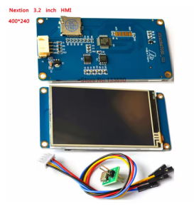
The Nextion Basic NX4024T032 is a powerful Human-Machine Interface (HMI) display module that integrates a 3.2-inch TFT LCD color screen with a resistive touch panel into a compact, easy-to-use package . Designed to provide seamless interaction between users and electronic systems, this module serves as an ideal control and visualization interface for IoT applications, consumer electronics, industrial automation, and embedded projects .
What sets the Nextion apart from traditional LCDs is its intelligent architecture. The module features a built-in processor that independently manages all graphical interface functions—drawing buttons, updating text, displaying graphs, and processing touch inputs—using its own firmware. Your main microcontroller (Arduino, ESP32, ESP8266, Raspberry Pi, or STM32) communicates with the display via simple ASCII text commands over a UART (TTL serial) interface . This approach eliminates the need for complex graphics programming and parallel wiring, drastically reducing development time.
The drag-and-drop Nextion Editor software (free download from the manufacturer) allows you to design your graphical user interface visually: simply place buttons, sliders, gauges, and text boxes on the canvas, assign properties, and compile . The resulting firmware file is uploaded to the display via microSD card or serial. The “Basic” series balances performance and cost, making it an excellent starting point for both beginners and professionals .
Key Features
-
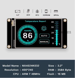
3.2-Inch TFT LCD Display: 400 × 240 pixel resolution (QVGA) with 65,536 colors (16-bit RGB 565), providing vivid, true-to-life visuals .
-
Integrated Resistive Touch Panel: Durable 4-wire resistive touch screen rated for over 1 million touches; responds to finger, gloved hand, or stylus input .
-
UART (TTL Serial) Communication: Simple 4-pin interface (VCC, GND, TX, RX) connects directly to Arduino, ESP32, ESP8266, Raspberry Pi, or STM32 .
-
Standalone HMI Processor: Built-in microcontroller handles all graphics processing and touch detection independently—your host MCU only needs to send simple commands .
-
WYSIWYG GUI Editor: Free, Windows-based Nextion Editor software with drag-and-drop components (buttons, text, sliders, progress bars, gauges) eliminates low-level graphics programming .
-
Adjustable Brightness: LED backlight brightness adjustable from 0% to 100% in 1% increments (up to 180 nits) via simple serial command .
-
Built-in Flash Memory: Stores fonts, images, and user interface data; supports microSD card (FAT32, up to 32GB) for firmware updates .
-
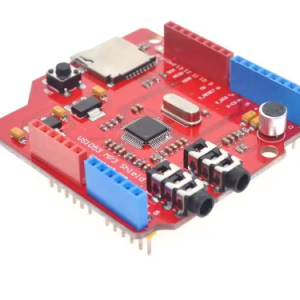
Wide Supply Voltage Range: Operates from 4.75V to 7.0V DC (5V typical), with a separate power test board included for verifying power supply capability .
-
Industrial Temperature Rating: Reliable operation from -20°C to +70°C, suitable for various indoor and protected outdoor applications .
-
Ultra-Low Power Consumption: Sleep mode consumes only 15mA during idle periods, ideal for power-sensitive applications .
Technical Specifications
Pinout & Connection Guide
The module uses a simple 4-pin, 2.54mm pitch header for all communication and power.
Pin Definitions
Wiring Diagrams
Arduino Uno / Mega (5V logic):
NX4024T032              →    Arduino Uno
──────────────────────────────────────────────
VCC                     →    5V
TXD                     →    RX (Pin 0)
RXD                     →    TX (Pin 1)
GND                     →    GND
ESP32 (3.3V logic):
NX4024T032              →    ESP32
──────────────────────────────────────────────
VCC                     →    External 5V Supply (not from ESP32)
TXD                     →    GPIO16 (RX2)
RXD                     →    GPIO17 (TX2)
GND                     →    GND
Note: Power the Nextion from a stable external 5V supply capable of delivering 500mA. The ESP32’s 3.3V pin cannot power the display directly .
USB-to-TTL Adapter (for PC debugging):
NX4024T032              →    USB-to-TTL Adapter
──────────────────────────────────────────────
VCC                     →    5V
TXD                     →    RXD
RXD                     →    TXD
GND                     →    GND
Usage Guide
1. Software Setup – Nextion Editor
Designing your user interface is a visual, drag-and-drop process using the free Nextion Editor software available from the official Nextion website .
Basic Workflow:
-
Create a New Project: Launch Nextion Editor, click “New,” select “Basic” as the series, and choose “NX4024T032” as the model .
-
Design Your Interface: Drag components (buttons, text boxes, sliders, progress bars, gauges) onto the page canvas.
-
Set Component Properties: Adjust colors, text, size, position, and other attributes.
-
Add Interactivity: In the Event pane for each component, enable “Send Component ID” to allow your host MCU to detect touch events .
-
Set Communication Baud Rate: In the Preinitialize Event of the first page, add the command: bauds=115200 (or your desired rate) to match your MCU .
-
Compile: Press F8 to compile the project and generate a .tft firmware file .
2. Uploading Firmware to the Display
-
Copy the compiled .tft file to a microSD card (FAT32 format, 32GB max) .
-
Ensure the card contains only one .tft file.
-
Power off the Nextion display.
-
Insert the microSD card into the display’s slot.
-
Power on the display. The firmware will upload automatically.
-
After completion, power off and remove the microSD card.
3. Host MCU Communication (Arduino Example)
Once your GUI is loaded, control the display from your Arduino using simple print statements. Every command sent to the Nextion must end with three bytes of 0xFF .
void setup() {
Serial1.begin(115200);
delay(3000);
}
void loop() {
Serial1.print("t0.txt=\"Hello World\"");
Serial1.write(0xFF); Serial1.write(0xFF); Serial1.write(0xFF);
delay(2000);
static int counter = 0;
counter++;
Serial1.print("n0.val=");
Serial1.print(counter);
Serial1.write(0xFF); Serial1.write(0xFF); Serial1.write(0xFF);
delay(1000);
}
4. Using the Iteadlib Arduino Library
The ITEADLIB_Arduino_Nextion library simplifies communication by handling the 0xFF terminators automatically .
Installation:
-
Download the library ZIP from GitHub.
-
In Arduino IDE: Sketch → Include Library → Add .ZIP Library.
Basic Library Example:
#include "Nextion.h"
NexText t0 = NexText(0, 1, "t0");
NexNumber n0 = NexNumber(0, 2, "n0");
void setup() {
nexInit();
}
void loop() {
t0.setText("Hello");
n0.setValue(42);
delay(1000);
}
5. ESP32 Setup Notes
When using the ESP32, configure the library for hardware Serial2 (pins GPIO16=TX, GPIO17=RX) in NexConfig.h :
#define nexSerial Serial2
Additionally, you may need to comment out #include <SoftwareSerial.h> and the NexUpload files as SoftwareSerial is incompatible with the ESP32 .
6. Detecting Touch Events
When a button with “Send Component ID” enabled is pressed, the Nextion sends a touch event code (e.g., 65 0 1 for button 0 on page 0). Your Arduino reads these from the serial buffer .
void loop() {
if (Serial1.available()) {
byte data = Serial1.read();
}
nexLoop(nex_listen_list);
}
Q: What is the difference between the Basic Series (NX4024T032) and the Enhanced Series (NX4024K032)?
The Basic Series (NX4024T032) is designed for standard HMI applications requiring display and touch functionality. The Enhanced Series (NX4024K032) adds features such as a Real-Time Clock (RTC), 1024 bytes of EEPROM, 8 digital GPIOs (4 PWM capable), and larger flash memory (16MB vs 4MB), making it suitable for standalone applications .
Q: Can I use this display with a 3.3V logic microcontroller like ESP32 without a level shifter?
The Nextion’s RXD pin is 5V tolerant and accepts 3.3V logic signals . The TXD pin outputs 3.3V logic, which is compatible with most 3.3V microcontrollers. However, the VCC pin must be powered by a separate 5V supply capable of delivering 500mA. Do not power the display from the ESP32’s 3.3V pin .
Q: Why is my display not responding to commands?
Check these common issues:
-
No firmware loaded: The display must have a valid .tft file flashed. The factory demo will not respond to commands .
-
Incorrect command termination: Every command must end with three bytes of 0xFF (or use the Iteadlib library) .
-
Baud rate mismatch: The default baud rate is 9600, but you can change it with the bauds= command in the HMI project’s Preinitialize Event. Ensure your host MCU matches .
-
Power supply: Ensure your 5V power supply can deliver at least 500mA.
Q: How do I change the baud rate of the Nextion display?
In your Nextion Editor project, add the command bauds=115200 (or your desired rate) to the Preinitialize Event of your first page. This sets the communication speed immediately when the display boots .
Q: What is the microSD card used for?
The microSD card slot is exclusively for upgrading the Nextion’s firmware (uploading your .tft GUI file). It cannot be used for data logging or storing images accessed by your host MCU .
Q: Is the Nextion truly "standalone" or does it always need a host MCU?
The Nextion is a smart display that can run simple logic using its internal processor and components (buttons, timers, etc.). For most IoT or complex control applications, it acts as a slave device, with an external MCU sending commands and receiving touch events. The Nextion handles the user interface; the MCU handles the application logic .
Q: Why is my display flickering or showing corrupt graphics?
This is almost always a power supply issue. The Nextion draws about 85mA with the backlight at 100%, with higher current spikes during startup. Ensure your power supply provides a stable 5V at 500mA. Also check that VCC and GND wires are securely connected .
Q: How do I send commands to the Nextion from my microcontroller?
Use simple print statements. For example, to set the text of a component named “t0” to “Hello”, send: t0.txt="Hello"\xFF\xFF\xFF (the three 0xFF bytes are the command terminator) .
Q: How do I detect that a button was pressed on the Nextion?
In the Nextion Editor, select your button component. In the Event pane, check the “Send Component ID” checkbox for the Touch Release Event (or Touch Press Event). Your microcontroller will receive a code (e.g., 65 0 1) when the button is touched .
Q: Can I update the display firmware without a microSD card?
Yes, it is possible to update the firmware over UART using the Iteadlib library’s NexUpload functionality, but this is more complex and less reliable than using a microSD card. The microSD method is the recommended and primary method