Product Overview
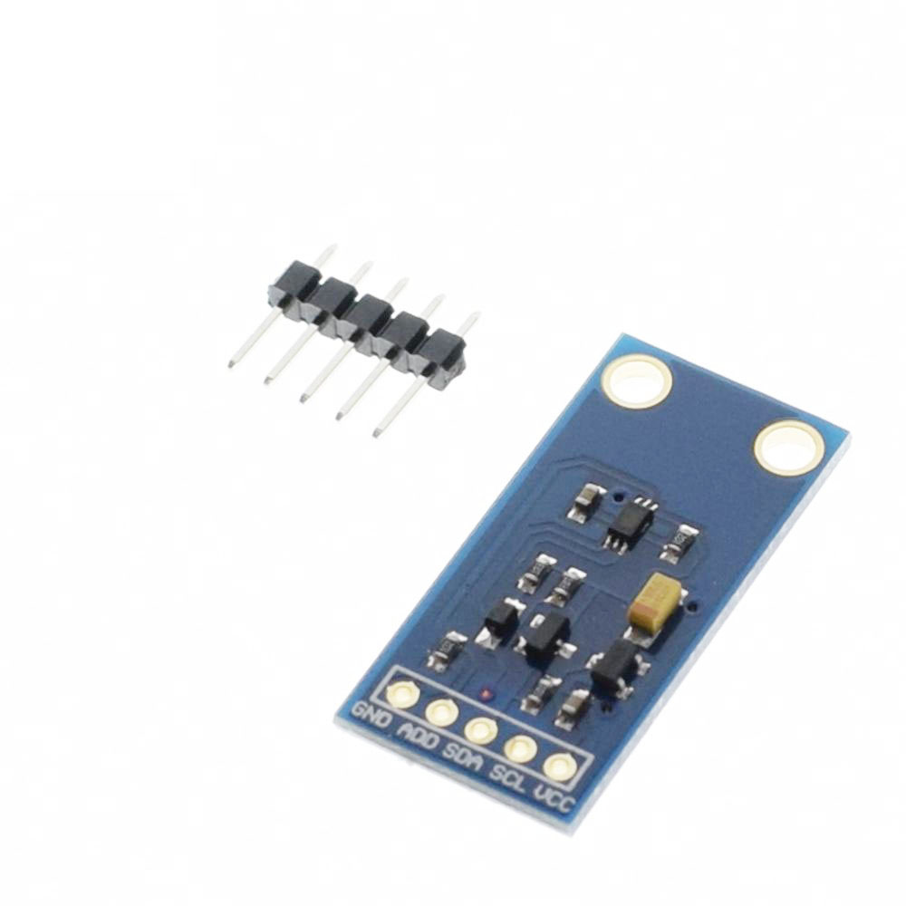
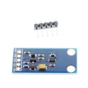
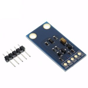
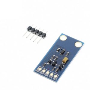
The GY-30 BH1750FVI Digital Light Intensity Sensor Module is a sophisticated ambient light sensor that provides direct digital output of illuminance (lux) levels via the I2C interface. Unlike traditional Light Dependent Resistors (LDRs) that require complex analog calculations, this module features a built-in 16-bit Analog-to-Digital Converter (ADC) and outputs calibrated light intensity data directly in lux—the standard unit of illumination .
Manufactured by ROHM Semiconductor, the BH1750FVI chip is designed to measure light intensity across an exceptionally wide dynamic range of 1 to 65,535 lux with high resolution . This capability makes it ideal for applications ranging from detecting dim moonlight (approximately 0.2 lux) to full direct sunlight (approximately 100,000 lux), covering virtually all practical lighting conditions encountered in daily use and industrial environments.
The sensor’s spectral response is specifically engineered to closely match the sensitivity of the human eye, peaking at approximately 560nm (green-yellow) . This human-eye-like response ensures that the sensor measures brightness as humans perceive it, rather than being influenced by infrared or ultraviolet light that typical photodiodes are sensitive to. The result is accurate, reliable light measurements that correlate with human visual perception.
Key features include selectable I2C slave addresses for multi-device configurations, 50Hz/60Hz flicker noise rejection for stable operation under artificial lighting, and a power-down mode that reduces current consumption to minimal levels when the sensor is inactive .
Whether you are building automatic screen brightness adjustment systems, greenhouse lighting controls, weather stations, or smart home automation, the GY-30 BH1750FVI module offers plug-and-play simplicity with accurate, repeatable results. The module includes onboard level shifting, making it directly compatible with both 3.3V and 5V microcontrollers such as Arduino, ESP32, ESP8266, Raspberry Pi, and STM32 without requiring external level converters .
Key Features
-
Direct Digital Output: Built-in 16-bit ADC outputs calibrated lux values—no complex analog calculations or calibration required
-
Wide Measurement Range: Detects illuminance from 1 to 65,535 lux, covering everything from dark rooms to bright sunlight
-
Human-Eye Spectral Response: Spectral sensitivity closely matches the human eye (peak sensitivity at approximately 560nm), providing accurate brightness measurements as perceived by humans
-
I2C Digital Interface: Simple 2-wire communication (SDA, SCL) with selectable slave addresses (0x23 or 0x5C via ADD pin configuration), allowing multiple sensors on the same bus
-
Dual Voltage Compatibility: Operates on 3V-5V power with onboard level shifting; directly compatible with both 3.3V (ESP32, ESP8266) and 5V (Arduino) microcontrollers
-
Extremely Low Power Consumption: Active measurement current as low as 120µA with power-down mode reducing consumption to near zero when idle
-
High Resolution Modes: Multiple measurement modes including high-resolution mode (1lx resolution, 120ms measurement time) and high-resolution mode 2 (0.5lx resolution for low-light conditions)
-
Built-in Noise Rejection: Integrated 50Hz/60Hz light noise rejection filters ensure stable readings under fluorescent and artificial lighting
-
No External Components Required: Fully self-contained sensor—no external resistors, capacitors, or calibration needed for operation
-
Low Measurement Variation: Maximum ±20% variation between units, ensuring consistent and repeatable performance across different sensors
Technical Specifications
Pinout & Connection Guide
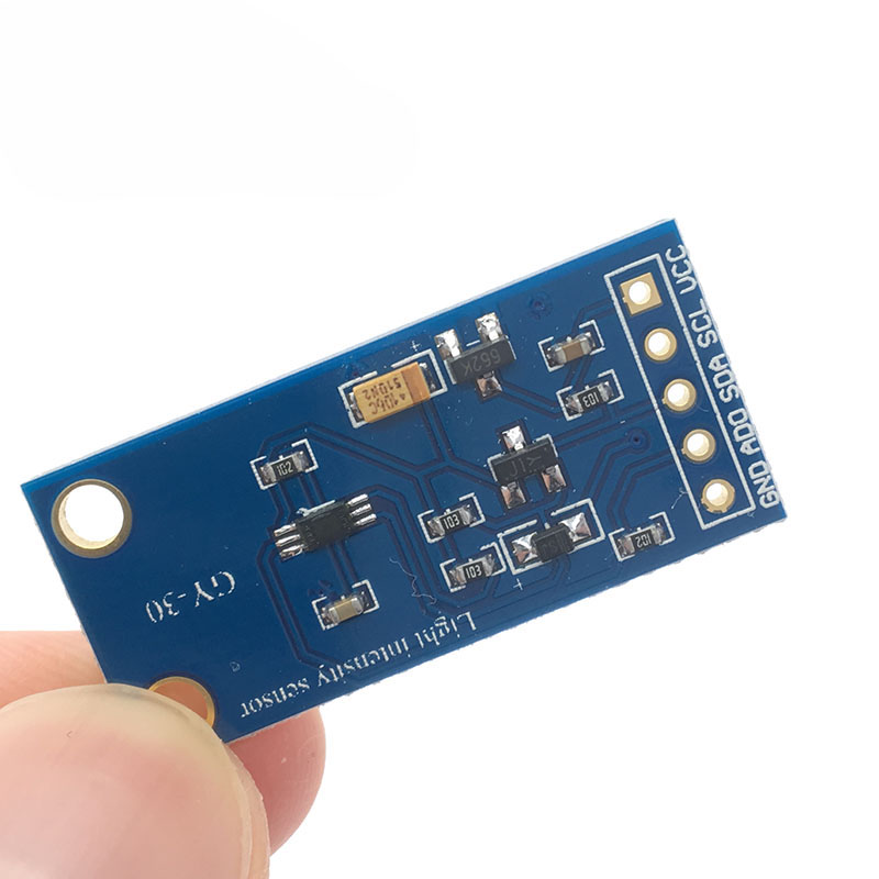
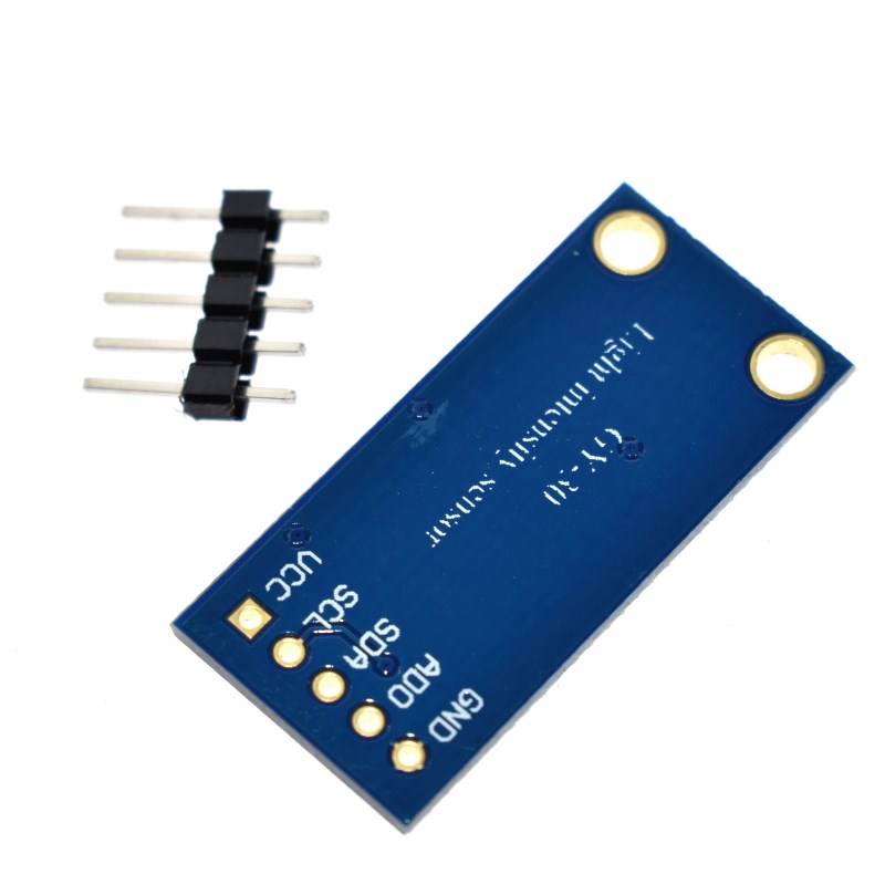
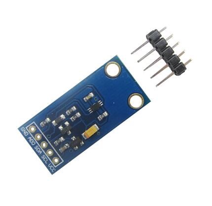
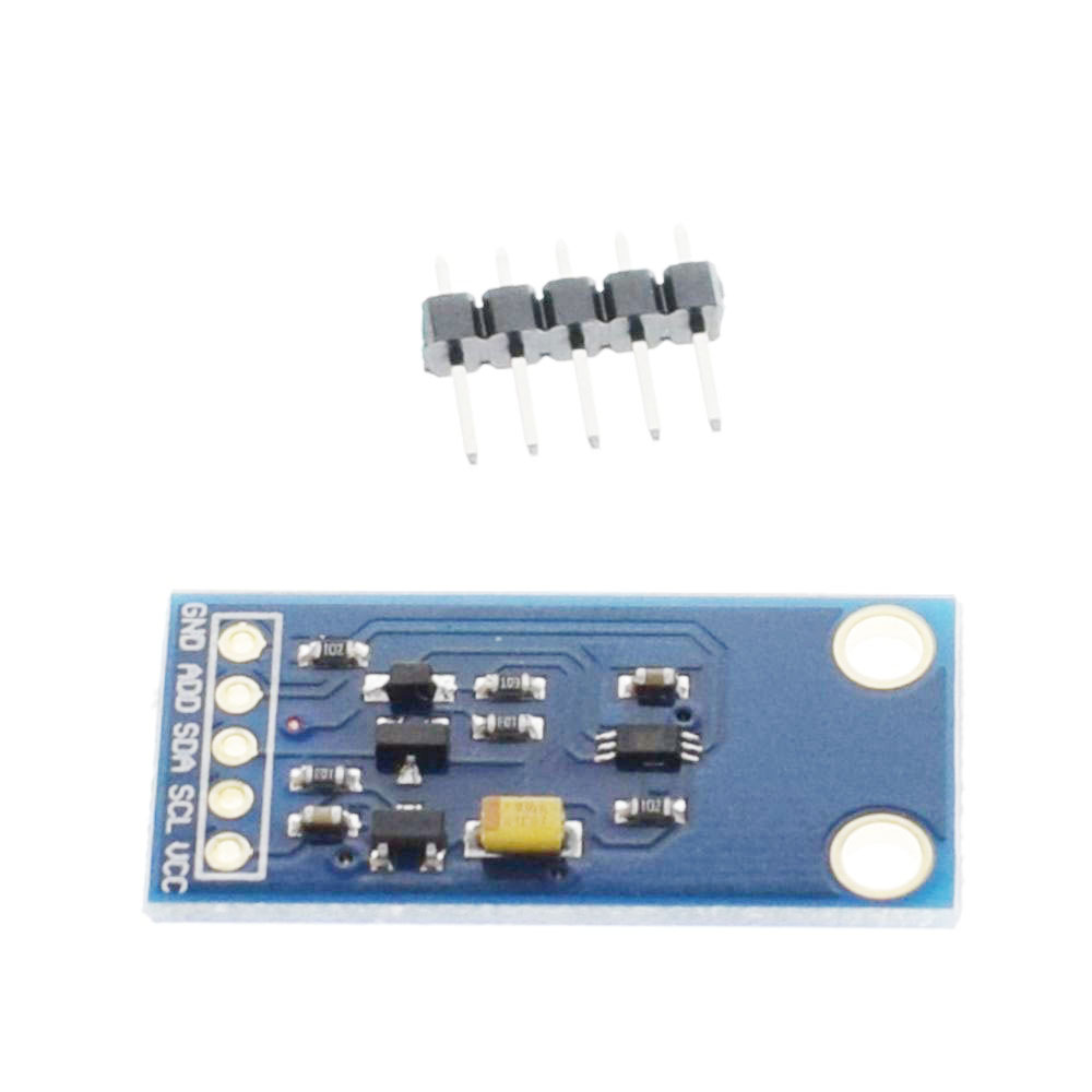
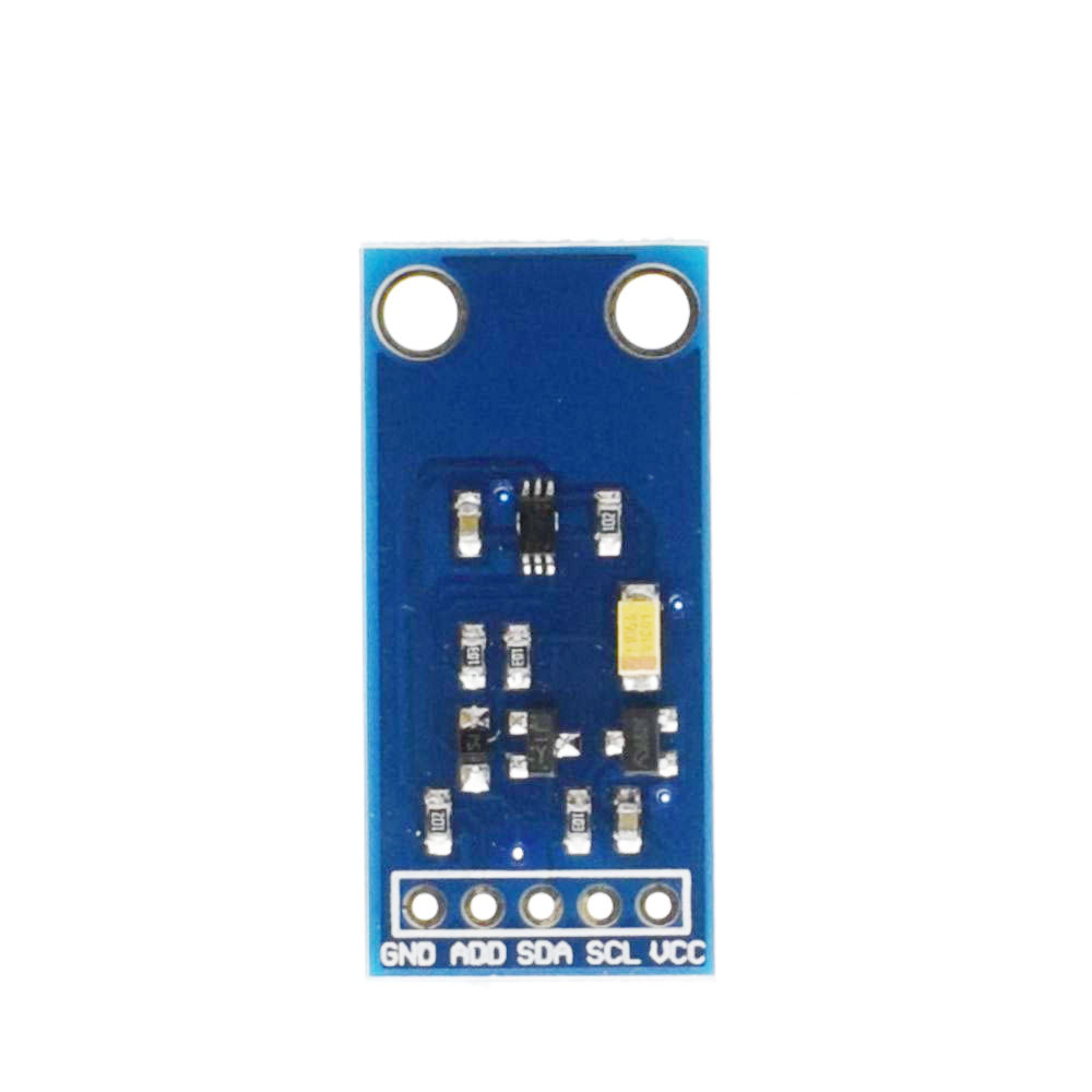
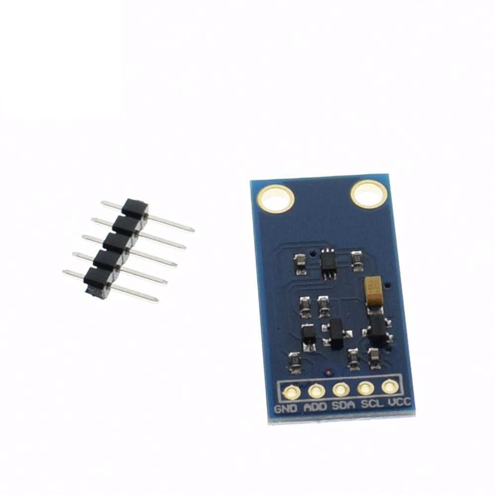
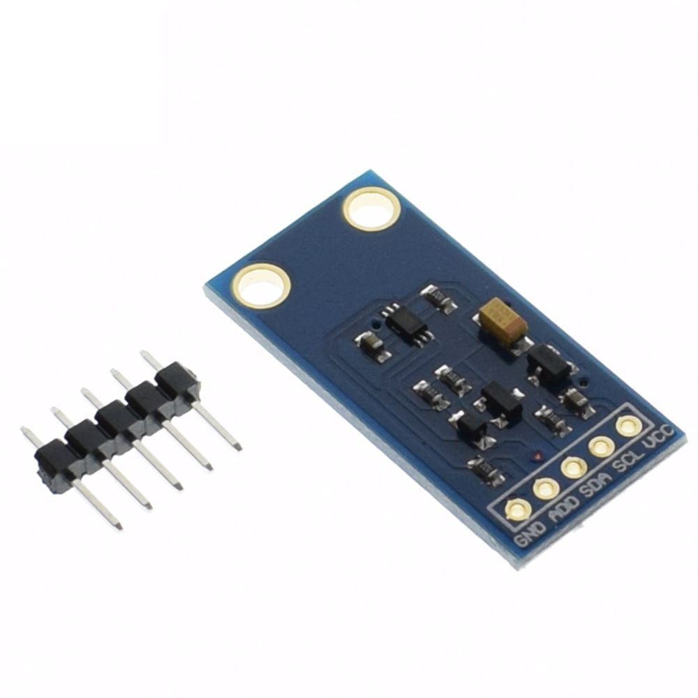
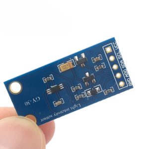
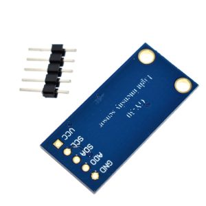
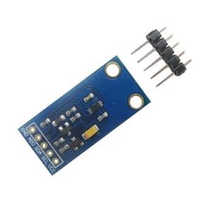
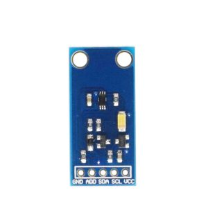
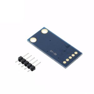
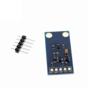
The GY-30 BH1750FVI module features a compact 5-pin configuration, clearly labeled on the PCB for easy wiring.
Pin Definitions
I2C Address Configuration
The ADD pin selects between two I2C slave addresses, allowing two BH1750 sensors to coexist on the same I2C bus :
I2C Pin Mapping for Common Development Boards
Wiring Diagram (Arduino Uno)
GY-30 Module          →    Arduino Uno
─────────────────────────────────────────
VCC                   →    5V
GND                   →    GND
SCL                   →    A5 (SCL)
SDA                   →    A4 (SDA)
ADD                   →    GND (for address 0x23) or leave unconnected
Pull-Up Resistor Requirements
The I2C bus requires pull-up resistors on the SDA and SCL lines. Most GY-30 modules include onboard 4.7kΩ pull-up resistors, but if you experience communication issues, adding external 4.7kΩ – 10kΩ resistors between SDA and VCC, and SCL and VCC, can improve reliability, especially with long cables or multiple I2C devices.
ADD Pin Configuration
-
For address 0x23: Connect ADD pin to GND
-
For address 0x5C: Connect ADD pin to VCC (3.3V or 5V)
-
Leave floating: Some modules default to 0x23 when unconnected; check your specific module documentation
Measurement Modes Explained
The BH1750FVI sensor offers multiple measurement modes, allowing you to optimize for resolution, speed, and power consumption:
Continuous Mode: The sensor continuously measures light intensity and updates the data register. Use this when you need constant monitoring .
One-Time Mode: The sensor performs a single measurement and then enters power-down mode. Use this for battery-powered applications where you only need periodic readings .
Resolution Trade-offs: Higher resolution modes (1lux and 0.5lux) provide greater accuracy but consume more power and take longer. Lower resolution mode (4lux) is faster and more power-efficient but less precise .
Usage Guide
Software Setup (Arduino IDE)
Step 1: Install Required Libraries
The BH1750 is compatible with several libraries. The most popular and well-maintained are:
Option A: “BH1750” Library (by Christopher – recommended)
-
Open Arduino IDE → Sketch → Include Library → Manage Libraries
-
Search for “BH1750”
-
Find the library by Christopher (claws) or Mario Ban and click Install
-
This library automatically includes I2C initialization and provides simple readLightLevel() function
Option B: “GY-30” Library
Option C: Manual I2C Implementation
Step 2: I2C Address Verification
Before writing code, verify your sensor’s I2C address. Run this scanner sketch:
#include <Wire.h>

void setup() {
  Wire.begin();
  Serial.begin(9600);
  Serial.println("I2C Scanner");
}

void loop() {
  byte error, address;
  int nDevices = 0;

  for(address = 1; address < 127; address++) {
    Wire.beginTransmission(address);
    error = Wire.endTransmission();

    if(error == 0) {
      Serial.print("I2C device found at address 0x");
      if(address < 16) Serial.print("0");
      Serial.println(address, HEX);
      nDevices++;
    }
  }

  if(nDevices == 0) Serial.println("No I2C devices found");
  delay(5000);
}
Expected output: Address 0x23 (or 0x5C if ADD pin is pulled HIGH).
Step 3: Basic Test Sketch
BH1750 GY-30 Light Intensity Sensor Basic Read Example
*/
#include <Wire.h>
#include <BH1750.h>
BH1750 lightMeter;
void setup() {
Serial.begin(9600);
Wire.begin();
if (lightMeter.begin(BH1750::CONTINUOUS_HIGH_RES_MODE)) {
Serial.println(F("BH1750 Sensor Initialized Successfully"));
Serial.println(F("Light intensity readings will start..."));
} else {
Serial.println(F("Error initializing BH1750 sensor! Check wiring."));
while (1);
}
}
void loop() {
float lux = lightMeter.readLightLevel();
Serial.print("Light Intensity: ");
Serial.print(lux);
Serial.println(" lx");
if (lux < 10) {
Serial.println(" (Very dark - night time or dark room)");
} else if (lux < 50) {
Serial.println(" (Dim light - twilight or dark indoor)");
} else if (lux < 200) {
Serial.println(" (Moderate indoor lighting)");
} else if (lux < 500) {
Serial.println(" (Bright indoor - office lighting)");
} else if (lux < 2000) {
Serial.println(" (Overcast day outdoors)");
} else {
Serial.println(" (Very bright - direct sunlight)");
}
delay(1000);
}
Step 4: Reading with Specific Measurement Mode
BH1750 Multi-Mode Example - Select different measurement modes
*/
#include <Wire.h>
#include <BH1750.h>
BH1750 lightMeter;
void setup() {
Serial.begin(9600);
Wire.begin();
lightMeter.begin();
}
void loop() {
float lux1 = lightMeter.readLightLevel(BH1750::ONE_TIME_HIGH_RES_MODE);
Serial.print("One-Time HR: "); Serial.print(lux1); Serial.println(" lx");
delay(500);
float lux2 = lightMeter.readLightLevel(BH1750::CONTINUOUS_HIGH_RES_MODE);
Serial.print("Continuous HR: "); Serial.print(lux2); Serial.println(" lx");
delay(500);
float lux3 = lightMeter.readLightLevel(BH1750::CONTINUOUS_LOW_RES_MODE);
Serial.print("Continuous LR: "); Serial.print(lux3); Serial.println(" lx");
delay(1000);
}
Raspberry Pi Setup (Python)
Step 1: Enable I2C Interface
-
Run sudo raspi-config → Interface Options → I2C → Enable → Reboot
-
Verify with sudo i2cdetect -y 1 – the sensor should appear at address 0x23
Step 2: Install Required Libraries
sudo apt-get install python3-smbus python3-pip
pip3 install RPi.bme280
Step 3: Python Example Code
import smbus
import time
BH1750_ADDR = 0x23
POWER_ON = 0x01
POWER_DOWN = 0x00
RESET = 0x07
CONTINUOUS_HIGH_RES_MODE = 0x10
CONTINUOUS_HIGH_RES_MODE_2 = 0x11
CONTINUOUS_LOW_RES_MODE = 0x13
ONE_TIME_HIGH_RES_MODE = 0x20
ONE_TIME_HIGH_RES_MODE_2 = 0x21
ONE_TIME_LOW_RES_MODE = 0x23
def read_light():
data = bus.read_i2c_block_data(BH1750_ADDR, CONTINUOUS_HIGH_RES_MODE, 2)
lux = ((data[0] << 8) | data[1]) / 1.2
return lux
bus = smbus.SMBus(1)
try:
while True:
light_level = read_light()
print(f"Light Intensity: {light_level:.2f} lx")
time.sleep(1)
except KeyboardInterrupt:
print("Measurement stopped")
MicroPython Setup (ESP32/ESP8266)
from machine import Pin, I2C
import bh1750
import time
i2c = I2C(0, scl=Pin(22), sda=Pin(21), freq=400000)
sensor = bh1750.BH1750(i2c)
while True:
lux = sensor.measure()
print("Light: {:.2f} lx".format(lux))
time.sleep(1)
Understanding the Output
-
1 – 10 lx: Very dark environment (night, dark room). Good for night-time monitoring applications.
-
50 – 200 lx: Dim indoor lighting (twilight, dark corners). Ideal for detecting when lights should be turned on.
-
200 – 500 lx: Standard indoor lighting (office, home). Typical range for screen brightness adaptation.
-
500 – 2,000 lx: Bright indoor (near window, bright office) or overcast outdoor.
-
2,000 – 10,000 lx: Full daylight outdoors (shade or overcast).
-
10,000 – 100,000 lx: Direct sunlight. Very bright conditions.
Power Management for Battery-Powered Projects
The BH1750’s low power consumption makes it excellent for battery-powered applications:
Power-Saving Code Example:
lightMeter.startMeasurement(BH1750::ONE_TIME_HIGH_RES_MODE);
delay(150);
float lux = lightMeter.getLux();
ESP.deepSleep(60 * 1000000);
Troubleshooting Common Issues
Q: What is the difference between BH1750 and an LDR (photoresistor)?
An LDR is an analog component that changes resistance based on light, requiring an ADC and calibration to convert to meaningful units. The BH1750 is a complete digital sensor with a built-in 16-bit ADC that outputs calibrated lux values directly without any calculations or calibration . Additionally, the BH1750’s spectral response matches the human eye, while LDRs are sensitive to a broader spectrum, making the BH1750 more accurate for applications that measure brightness as humans perceive it.
Q: Can the BH1750 measure very low light levels (moonlight)?
Yes, with a limitation. The standard measurement range starts at 1 lux, which is slightly higher than typical moonlight (approximately 0.2 lux). However, by adjusting the measurement time register (MTreg), you can detect light levels as low as 0.11 lux, enabling moonlight detection . This requires modifying the sensor’s configuration registers for extended range operation.
Q: What is the maximum light intensity this sensor can measure?
The standard measurement range is 1 – 65,535 lux. By using the optical window correction feature and adjusting the measurement time, you can measure up to 100,000 lux, which covers direct sunlight conditions . This makes the sensor suitable for both indoor dim light and outdoor bright sunlight applications.
Q: How do I use two BH1750 sensors on the same I2C bus?
Each BH1750 has two possible I2C addresses (0x23 and 0x5C). Set the ADD pin of one sensor to GND (0x23) and the ADD pin of the second sensor to VCC (0x5C) . Both sensors share the same SDA and SCL lines. This configuration allows independent reading from both sensors on the same bus, perfect for applications requiring light measurement from multiple directions.
Q: Why does my sensor sometimes return 0 lux when it shouldn't?
This can occur if:
-
You’re using readLightLevel() without first calling begin() to initialize the sensor
-
The measurement mode is not properly configured—ensure you’re using a mode that actually performs measurements (e.g., CONTINUOUS_HIGH_RES_MODE)
-
The ADD pin is floating—connect it to GND or VCC for a stable address
-
Power supply noise is affecting readings—use a stable 5V/3.3V source and add a 0.1µF decoupling capacitor near the module’s VCC pin
Q: What is the purpose of the "Continuous" vs "One-Time" measurement modes?
Continuous mode keeps the sensor active and continuously updates the lux reading. Use this when you need constant monitoring (e.g., a light meter display). One-Time mode performs a single measurement, then the sensor enters power-down mode automatically. Use this for battery-powered applications where you only need periodic readings (e.g., once per minute), as it significantly reduces average power consumption .
Q: Can this sensor be used outdoors or in automotive applications?
Yes, the BH1750 has an industrial operating temperature range of -40°C to +85°C . This makes it suitable for outdoor installations (weather stations, solar tracking) and automotive interior applications (automatic mirror dimming, ambient lighting control). However, the module itself is not waterproof—for outdoor use, place it inside a weatherproof enclosure with a transparent window.
Q: How accurate are the lux readings?
The typical measurement variation between different BH1750 units is ±20% . This is due to variations in the photodiode sensitivity and optical window characteristics. For most consumer applications (screen brightness adjustment, lighting control), this accuracy is sufficient. For scientific applications requiring higher precision, you would need to calibrate individual sensors against a known reference light source.
Q: What is the "Optical Window" feature and when should I use it?
The optical window feature compensates for attenuation caused by a physical window or cover placed over the sensor . For example, if you enclose the sensor in a weatherproof box with 50% light transmission, you can configure the sensor to multiply readings by 2x to compensate. This is done by adjusting the MTreg (measurement time register) value—doubling the register value effectively doubles sensitivity, compensating for optical losses .
Q: What is the maximum I2C communication speed?
The BH1750 supports both Standard Mode (100 kHz) and Fast Mode (400 kHz) I2C speeds . Most microcontroller libraries default to 100 kHz for maximum compatibility. You can increase to 400 kHz for faster communication, but ensure your pull-up resistor values are appropriate (typically 4.7kΩ for 400 kHz operation). For ESP32/ESP8266, the default I2C frequency is typically 100 kHz; you can adjust it using Wire.setClock(400000).
Q: The measurement values seem too high or too low. How can I calibrate the sensor?
The BH1750 does not require calibration for normal use, but you can adjust readings in software if needed:
-
For consistent offset, apply a multiplication factor in your code
-
For different measurement time settings, the lux calculation formula changes—ensure your library accounts for this
-
For optical window attenuation, use the MTreg adjustment method described in the datasheet
Q: What is the response time of the sensor?
The measurement time for high-resolution mode is approximately 120 milliseconds . For low-resolution mode, the measurement time is approximately 16 milliseconds . This includes the ADC conversion time. For applications requiring faster response (e.g., detecting rapid light changes), use the low-resolution mode or one-time measurement modes with shorter integration times.