Product Overview
The XL4016 300W Buck Converter is a high-performance, adjustable DC-DC step-down (buck) power module designed for applications demanding efficient voltage regulation at high currents. Based on the XL4016E1 chip from XLSEMI, this module features a built-in constant current (CC) and constant voltage (CV) control loop, making it incredibly versatile for a wide range of uses, from powering high-wattage LED arrays to charging lithium batteries .
Unlike standard voltage-only regulators, this module allows you to independently adjust both the output voltage and the output current limit. This “CC/CV” characteristic is essential for safely charging batteries and driving high-power LEDs without risk of overcurrent . With an input range of 7V to 40V DC and an adjustable output of 1.2V to 35V DC, it can handle up to 300W of power (with adequate cooling), delivering a continuous current of up to 9A .
The module operates at a high switching frequency (300kHz or 180kHz depending on version), which allows for smaller external components and low output ripple, ensuring stable power for sensitive electronics . It is equipped with a multi-turn potentiometer for precise voltage adjustment and another for current limiting, along with a dual-color LED indicator that shows whether the module is in constant current (CC) mode or constant voltage (CV) mode .
Key Features
-
High Power & Current Capacity: Supports a maximum output power of approximately 300W and can deliver a continuous output current of up to 9A (8A continuous recommended, 9A peak) .
-
CC/CV (Constant Current/Constant Voltage) Control: This dual-mode regulation allows the module to function as a standard voltage regulator (CV) or as a current limiter (CC), essential for battery charging and LED driving .
-
Wide Adjustable Ranges: Input accepts DC 7-40V (up to 40V absolute max), output is continuously adjustable from 1.2V to 35V. The current limit is adjustable from 0.2A to 9A .
-
High-Efficiency Conversion: Achieves a conversion efficiency of up to 95% (varies with input/output differential), minimizing energy loss and heat generation .
-
Low Output Ripple: Output ripple is around 50mV (under typical conditions), making it suitable for low-noise analog circuits .
-
Built-in Protection Features:
-
Output Short Circuit Protection (Constant Current limiting) .
-
Thermal Shutdown Protection (chip-level) .
-
Input Reverse Polarity Protection: Not included (requires external diode) .
-
Versatile Applications: Ideal for use as a high-power LED driver, lithium battery charger (1S-6S), adjustable bench power supply, or voltage regulator for motors and DIY projects .
-
Dual-Color Status Indicator: A red LED indicates Constant Current (CC) mode, while a green LED indicates Constant Voltage (CV) mode.
Technical Specifications
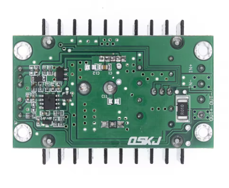
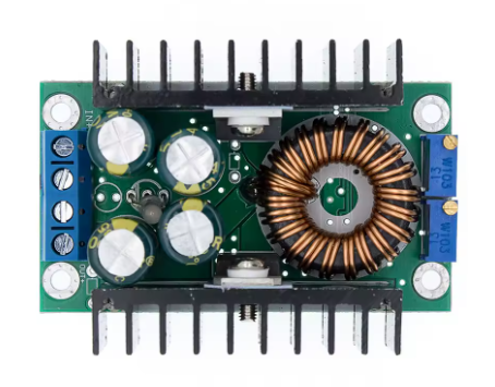
Pinout & Interface Guide
The module uses clear terminal blocks for input and output connections, plus potentiometers for adjustment.
Terminal Blocks
User Adjustments
Critical Safety Warning: This module does NOT have input reverse polarity protection. Connecting the input power with reversed polarity will instantly destroy the module. Always double-check your wiring before applying power and consider adding a series diode for protection.
Usage Guide
Important Preliminary Steps
⚠️ Use a Multimeter: The default factory output is often set to a random high voltage. Always measure the output with a multimeter before connecting your load. Adjust the CV potentiometer to the exact voltage required by your device to avoid damage.
Wiring Instructions
-
Set Initial Outputs: Before powering on, turn both the CV (voltage) and CC (current) potentiometers counter-clockwise about 10-15 turns to set them to their minimum positions.
-
Connect Input: Connect your DC power source (7-40V) to the IN+ and IN- terminals. Ensure correct polarity.
-
Set Voltage (CV Mode): With a multimeter on the output terminals, slowly turn the CV potentiometer clockwise until you reach your desired output voltage (leave CC at minimum).
-
Set Current Limit (CC Mode): This step is crucial for battery charging or LED driving.
-
Method A (Short Circuit): With input power off, connect an ammeter directly across the OUT+ and OUT- terminals (short circuit). Power on the module. Slowly turn the CC potentiometer clockwise until the meter reads your desired current limit. Power off and remove the ammeter.
-
Method B (Calculated Load): Connect a dummy load that draws the desired current. Power on the module and adjust the CC potentiometer while monitoring the current.
-
Connect Load: Turn off input power, connect your permanent load (battery, LED, etc.) to the OUT+ and OUT- terminals, and then re-apply power.
CC/CV Operation & LED Indicator
The module’s operating mode is indicated by the onboard LED:
Thermal Management
The maximum output power depends heavily on cooling:
When the power transistor temperature exceeds 65°C, a cooling fan is mandatory to prevent overheating and ensure reliable operation .
Typical Applications
Q: What is the difference between Constant Current (CC) and Constant Voltage (CV) mode?
CV mode regulates voltage; the module holds the output steady at the set voltage, and the load determines how much current to draw. CC mode regulates current; the module limits the current to the set value, and the voltage drops as needed to maintain that limit. The CC/CV combination is essential for battery charging (CC to fill, CV to top-off) and LED driving (CC to prevent thermal runaway) . The red LED indicates CC mode, the green LED indicates CV mode
Q: Why does my output voltage drop when I connect a load?
This usually happens for one of two reasons:
-
The module is in CC mode: The load is trying to draw more than the set current limit (e.g., a dead battery or a high-power motor). Increase the CC limit or check the load’s specifications. The red LED being lit confirms this.
-
Input power drop: Your input source or wires cannot supply the required current. Use thicker wires and verify your input voltage stays stable under load.
Q: Can I use this module to charge a lithium-ion battery?
Yes, absolutely. This is one of its primary functions. Set the output voltage to the battery’s “float” voltage (4.2V per cell). Set the CC limit to the maximum safe charge current for your battery (usually 0.5C to 1C). The module will perform a complete CC/CV charge cycle automatically .
Q: The module gets very hot. Is this normal?
At power levels above 150W, the module will generate significant heat. The built-in heatsink is sufficient for 150W. However, to reach 300W, an external 12V cooling fan is mandatory. Also, ensure good ambient airflow .
Q: What is the purpose of the two potentiometers?
The potentiometer near the input side is for CV (Voltage) adjustment. The potentiometer near the output side is for CC (Current) adjustment. The CV pot sets the max voltage; the CC pot sets the max current .
Q: Does this module have short circuit protection?
Yes, it has output short circuit protection. If you short the output, the module enters constant current (CC) mode and limits the current to the set value, preventing damage .
Q: Does this module have reverse polarity protection?
NO. This module does NOT have input reverse polarity protection. Connecting the input voltage backwards will instantly destroy the module. Always double-check your wiring .
Q: Can I use this module to get 3.3V or 5V from a 12V battery?
Yes. This is an ideal application. Set the CV pot to 5.0V or 3.3V, and set the CC pot to its maximum. The module will then act as a high-efficiency 5V regulator.
Q: What is the maximum input voltage I can safely apply?
The maximum input voltage is 40V DC. It is recommended to stay below 38V for a safety margin. Do not exceed 40V .
Q: Can I use this to power a 12V DC motor?
Yes, however, DC motors have very high inrush currents (stall current). You will need to set the CC limit high enough to handle the motor’s starting surge, or the module will go into CC mode and the motor may not start spinning.