EGS002 Pure Sine Wave Inverter Drive Board – Dedicated LCD Display Module

SKU: FA2175-1
Display Type

LCD (Liquid Crystal Display)

Controller IC

ST7920 (compatible with EG8010)

Resolution

128 × 32 pixels

Interface

Serial (7-pin)

Operating Voltage

5V DC

Backlight Supply

5V DC (LED+ / LED- pins)

Connection Cable

110mm (ribbon cable, shielding recommended for high-power use)

Dimensions (L×W×H)

35mm × 22mm × 12mm

Description

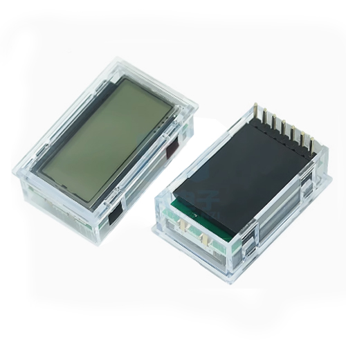
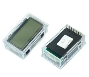
The EGS002 Dedicated LCD Display Module is an optional but highly recommended accessory for the EGS002 pure sine wave inverter driver board. This compact serial LCD display provides real-time visual monitoring of critical inverter parameters, transforming your inverter project from a “black box” into a fully observable, manageable system .

Compatible with the EG8010 ASIC at the heart of the EGS002 driver board, this display connects via a simple 7-pin serial interface and requires no additional programming or microcontroller. It leverages the EG8010’s built-in LCD driver functionality, allowing users to monitor output voltage, output frequency, system temperature, and fault conditions at a glance .

The display is based on the widely supported ST7920 controller IC and features a 128×32 pixel resolution, providing clear, legible readouts even from a distance . With a compact 35mm × 22mm footprint and an included 110mm ribbon cable (shielding recommended for high-power installations), this LCD module is designed for seamless integration into DIY inverter enclosures, solar power systems, UPS backups, and wind power installations .

The EG8010 chip integrates a dedicated serial LCD unit that supports both the 12832 LCD (default) and the LCD3220 variant. Without an LCD, the EGS002 board still functions perfectly, but adding this display unlocks the full diagnostic and monitoring potential of your pure sine wave inverter .

Key Features

  • Real-Time System Monitoring – Displays output voltage, frequency, temperature, and current status in real-time .

  • EG8010 Native Compatibility – Specifically designed to interface with the EG8010’s built-in serial LCD driver; plug-and-play compatible with the EGS002 driver board .

  • ST7920 Controller IC – Based on a widely available and well-documented controller, ensuring easy replacement and broad compatibility .

  • 128×32 Pixel Resolution – High-contrast display for clear visibility of numbers and status icons even in varying lighting conditions.

  • Serial Communication Interface – Simple 7-pin connection (VCC, GND, DI, CLK, CS, LED+, LED-) reduces wiring complexity compared to parallel LCDs .

  • Fault Indication Support – Integrates with the EGS002’s warning system to visually indicate over-voltage, under-voltage, over-current, and over-temperature conditions .

  • Backlit Display – Includes LED backlight control (LED+/LED- pins) for easy readability in low-light environments .

  • No Programming Required – Fully hardware-driven by the EG8010 chip; no firmware development or microcontroller coding needed to display standard parameters.

  • Compact Size – Small form factor (approx. 35mm × 22mm) fits easily into standard inverter enclosures .

Technical Specifications 

Specification Value
Display Type LCD (Liquid Crystal Display)
Controller IC ST7920 (compatible with EG8010) 
Resolution 128 × 32 pixels 
Interface Serial (7-pin) 
Operating Voltage 5V DC 
Backlight Supply 5V DC (LED+ / LED- pins) 
Connection Cable 110mm (ribbon cable, shielding recommended for high-power use) 
Dimensions (L×W×H) 35mm × 22mm × 12mm 

Typical Usage

  • Solar Power Inverters – Monitor real-time AC output and system status for home solar installations.

  • Uninterruptible Power Supply (UPS) Systems – Provide visual feedback during power backup operations.

  • Wind Power Generation – Track voltage and frequency stability in variable wind conditions.

  • DIY Inverter Projects – Add professional-grade monitoring to homemade pure sine wave inverters.

  • Digital Generators – Serve as the user interface panel for portable inverter generators.

  • Single-Phase Motor Speed Controllers – Verify output frequency adjustments when driving AC motors.

  • Educational Demonstrations – Visually demonstrate SPWM inverter operation in laboratory settings.

  • Remote Monitoring Setups – Use with extended shielded cables to place the display on equipment panels away from high-power sections .

Q: Is this LCD display required for the EGS002 board to function?

No. The EGS002 driver board operates perfectly without the LCD. The display is an optional monitoring accessory that provides real-time visibility into voltage, frequency, temperature, and fault status. For basic inverter operation, the LCD is not required .

Q: Is the display plug-and-play with the EGS002 board?

Yes. The EGS002 board includes a dedicated 7-pin LCD interface header. Simply connect the matching pins (1 to 1, 2 to 2, etc.) using the provided ribbon cable. Ensure correct orientation; most cables are keyed or color-coded .

Q: What type of LCD controller is compatible with the EG8010?

The EG8010 chip is designed to support most 12832 LCDs based on the ST7920 controller IC . It also specifically supports the LCD3220 variant, but the default is the 12832 model. Always verify the controller chip if purchasing a third-party replacement.

Q: How do I connect the LCD to the EGS002?

The 7-pin interface connects as follows: Pin 1 (+5V) to VDD, Pin 2 (GND) to VSS, Pin 3 (DI/SDI) to serial data, Pin 4 (CLK/SCLK) to serial clock, Pin 5 (EN/CS) to chip select, Pin 6 (LED+) to +5V, and Pin 7 (LED-) to GND . Standard ribbon cables usually follow this direct pin-to-pin mapping.

Q: Do I need a shielded cable for the LCD connection?

In high-power inverter environments (high voltage and high current), electromagnetic interference can disrupt LCD operation. A shielding cable is strongly recommended for the connection between the EGS002 driver board and the LCD to prevent erratic display behavior .

Q: What information does the LCD display show?

The LCD typically displays the inverter’s output voltage (e.g., 110V/220V), output frequency (50Hz/60Hz), system temperature, and fault codes or status indicators such as over-voltage, over-current, or under-voltage warnings .

Q: Can I use a 1602 LCD with the EGS002?

While some EG8010 documentation references 1602 LCD support, the standard and default configuration for the EGS002 driver board is the 12832 serial LCD based on the ST7920 controller . Compatibility with 1602 displays is not guaranteed without specific configuration changes.

Q: Does this display require separate power?

The display receives its operating power (5V) directly from the EGS002 driver board through the interface cable. The backlight also draws power from the 5V line via the LED+ and LED- pins. No external power supply is needed .

Q: What do the different LED blink patterns mean on the EGS002?

The EGS002 board has a red LED that indicates fault status:

  • Always ON: Normal operation.

  • Blinks twice, off 2 seconds: Over-current protection (OCP).

  • Blinks three times, off 2 seconds: Over-voltage protection (OVP).

  • Blinks four times, off 2 seconds: Under-voltage protection (UVP).

  • Blinks five times, off 2 seconds: Over-temperature protection (OTP) .

Q: Can I extend the cable length beyond the standard 110mm?

Yes, but with caution. In high-power inverter environments, longer cables are more susceptible to electromagnetic interference. If extending the cable, use a shielded cable and keep the distance as short as possible to maintain signal integrity .