T42 ATtiny Development Programmer Board: All-in-One DIP Platform
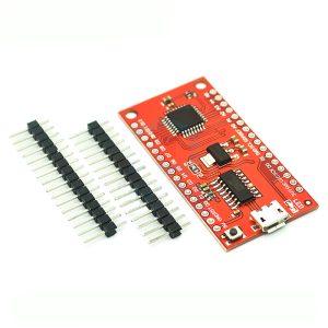
The T42 ATtiny Development Programmer Board is an integrated, all-in-one solution designed for rapid prototyping and programming of Microchip’s popular ATtiny series of microcontrollers in a convenient DIP (Dual Inline Package) format.
This board eliminates the need for external breadboards, complex wiring setups, or separate programmer shields by providing a dedicated socket, power regulation, user feedback components (LEDs and a button), and standard programming headers (ICSP/SPI) right on one small platform. It supports a wide range of common 8-pin ATtiny MCUs, including the ATtiny13A, ATtiny25, ATtiny45, and ATtiny85.
It serves as an excellent learning platform for those new to microcontrollers, and a fast development tool for engineers looking to drop an 8-pin ATtiny into a project without the hassle of temporary wiring.
Key Features
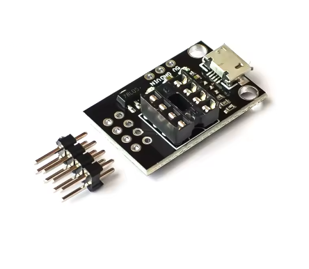
Universal DIP8 Socket: Features a ZIF (Zero Insertion Force) socket or a standard DIP8 socket configured to accept ATtiny13A, 25, 45, and 85 microcontrollers.
Integrated ICSP/SPI Header: Includes a standard 6-pin In-Circuit Serial Programming (ICSP) header to easily connect external programmers (like an Arduino as ISP or a dedicated AVR programmer).
Onboard Peripherals: Includes integrated components such as user LEDs, a push button, and power circuitry, which can be connected/disconnected via jumpers to test code immediately upon programming.
Power Flexibility: Can be powered via the ICSP header itself or an external power input (e.g., USB or DC jack depending on version), often including onboard 5V regulation.
Compact & Breadboard-Friendly: Small footprint makes it easy to integrate into existing breadboard setups or small project boxes during development.
Arduino IDE Compatibility: Fully programmable using the familiar Arduino IDE with the appropriate ATtiny core software package, making it accessible for a massive user base.
Technical Parameters (Specifications)
Parameter
Value/Description
Compatible MCUs (DIP8)
ATtiny13A, ATtiny25, ATtiny45, ATtiny85
Programming Interface
Standard 6-Pin ICSP/SPI Header
Input Voltage
Typically 5V DC (via ICSP or USB-B/Mini-USB port on the board)
Logic Level
5V TTL (Operating voltage of the compatible MCUs)
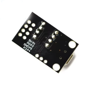
Onboard Components
User LED(s), Push Button, Power LED, Reset Circuit
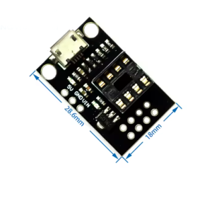
Dimensions
(Compact, typically around 3cm x 4cm)
Crystal Support
Often includes pads for an external crystal if desired (defaults to internal oscillator)
Usage Instructions
This board is primarily used as a development platform that requires an external programmer to flash code onto the ATtiny chip seated in the socket.
Step 1: Programming Hardware Setup
Insert ATtiny Chip: Place your ATtiny13A/25/45/85 chip carefully into the DIP8 socket, ensuring Pin 1 (marked by a dot or notch) aligns with the board’s marking.
Connect Programmer: Connect your external programmer (e.g., a USBasp or an Arduino configured as an ISP) to the 6-pin ICSP header on the T42 board using a standard ribbon cable.
Power: Power the setup (usually the programmer provides the 5V power via the ICSP cable).
Step 2: Software Setup (Using Arduino IDE)
Install ATtiny Core: Follow online tutorials to install the appropriate ATtiny board definitions in your Arduino IDE Boards Manager.
Select Board: Choose the correct target (e.g., “ATtinyX5 (Digispark/micronucleus)” or similar for the 45/85) and internal clock speed (usually 8 MHz).
Select Programmer: In the IDE under Tools -> Programmer, select your specific programmer (e.g., “Arduino as ISP” or “USBasp”).
Upload Code: Write your code, and instead of clicking the standard “Upload” button, go to Sketch -> Upload Using Programmer.
Step 3: Testing & Deployment
Once programmed, you can test the code using the onboard button/LEDs or move the programmed chip to its final application circuit.
Q: Do I need a separate programmer device to use this board?
Yes. This T42 board is a development platform or adapter, not a programmer itself. It provides the socket and connections for an external programmer (like a USBasp, AVR Pocket Programmer, or an Arduino Uno running the ISP sketch).
Q: Which ATtiny chips are compatible with this board?
It is designed for 8-pin DIP packages: specifically the ATtiny13A, ATtiny25, ATtiny45, and ATtiny85.
Q: Can I use this board without an external programmer if I have a Digispark (micronucleus bootloader) already installed on my ATtiny85?
If your specific board version includes a micro-USB port and the chip has the micronucleus bootloader fused, you can program it directly via USB. However, the primary function relies on the ICSP header for standard AVR programming methods.
Q: I am a business buyer. Is this suitable for high-volume production programming?
For high-volume production, dedicated universal gang programmers or in-fixture programming setups are usually more efficient. This T42 board is an excellent, reliable tool for engineering development, testing, and prototyping before mass production. Bulk pricing is available for R&D lab purchases.