Laqiya DSO138 2.4″ TFT Digital Oscilloscope 1Msps + Probe Analog Bandwidth (Need DIY)

SKU: FA1061-0
Microprocessor

ARM Cortex-M3 (STM32F103C8)

Display

2.4-inch Color TFT LCD (320 x 240)

Max Sampling Rate

1Msps

Analog Bandwidth

0 – 200KHz

Sensitivity Range

10mV/Div – 5V/Div

Max Input Voltage

50Vpk (1:1 probe)

Input Impedance

1MΩ / 20pF

Resolution

12 Bit

Record Length

1024 points

Power Supply

9V DC (Range: 8V – 12V)

Coupling Modes

DC / AC / GND

Product Description
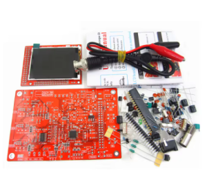
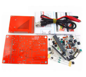
The Laqiya DSO138 DIY Kit is the gold standard for educational electronics projects in 2026. It is a partially open-source digital oscilloscope designed specifically for students, makers, and hobbyists who want to understand the inner workings of electronic measurement tools. By assembling this kit, users gain hands-on experience with soldering, circuit layout, and signal processing.
The heart of the device is an ARM Cortex-M3 processor (STM32F103C8), providing a responsive 2.4-inch color TFT display for clear waveform analysis. While it arrives as a kit requiring assembly, all the sensitive Surface Mount Devices (SMD) are typically pre-soldered on the board, leaving the user to master through-hole soldering for the connectors, switches, and large capacitors. Once built, it serves as a fully functional 200KHz oscilloscope, perfect for audio testing, PWM analysis, and learning the fundamentals of digital signal capture.

Key Features
  • Educational DIY Project: Designed to teach soldering and circuit theory. Provides a deep sense of accomplishment and a functional tool upon completion.
  • Vivid 2.4″ Color TFT: High-contrast display featuring a grid for precise waveform measurement and clear real-time parameter readouts.
  • Digital Trace Waveform: Includes “Hold” functionality to freeze waveforms for detailed inspection and measurement.
  • Pre-soldered SMD Components: To ensure a high success rate, the complex integrated circuits are pre-installed; users only need to solder the through-hole components.
  • Built-in Test Signal: Features a 1KHz / 3.3V square wave output for self-testing and probe calibration.
  • Comprehensive Data: Automatically calculates and displays frequency, period, pulse width, duty cycle, Max/Min, and Peak-to-Peak values.
Usage & Assembly Guide
  1. Preparation (DIY): Use a fine-tip soldering iron (25W-40W) and high-quality solder. Follow the included schematic to install components from lowest height to highest (resistors first, then electrolytic capacitors and switches).
  2. Powering On: Connect a stable 9V DC power source. If the screen lights up and displays a trace, the assembly was successful.
  3. Calibration: Connect the included probe to the BNC jack. Clip the probe tip to the 1KHz square wave test terminal on the board. Use the [SEL] and [+] buttons to center the waveform.
Q: Does this kit require advanced soldering skills?

This is considered an Intermediate level kit. Because the difficult SMD chips are pre-soldered, you only need to be comfortable with through-hole soldering. It is an ideal “next step” project for those who have mastered basic LED kits.

Q: Can I use this for professional automotive or mains electrical work?

No. This device is intended for low-voltage electronic circuits (up to 50Vpk). It is perfect for sensors, audio signals, and Arduino/Raspberry Pi projects, but is not rated for high-voltage industrial or automotive ignition systems.

Q: Is this suitable for educational institutions or STEM programs?

Absolutely. It is one of the most popular kits for university labs and high school electronics clubs because it results in a useful tool that students can keep and use for future projects.

Q: Why is my waveform a flat line?
1) Ensure the coupling switch is set to DC or AC, not GND.
2) Check that the voltage scale is appropriate for the signal. 3) Verify that your soldering on the BNC connector and input circuit is solid.
Q: Does it come with an enclosure?

This listing is for the board and components. While many users 3D print their own cases, we also offer a separate DSO138 Acrylic Case Kit to protect the device

Q: What power supply should I use?

Use a 9V DC (Center Positive) regulated power adapter. Avoid using poor quality “wall warts” as they can introduce significant electrical noise into your measurements.