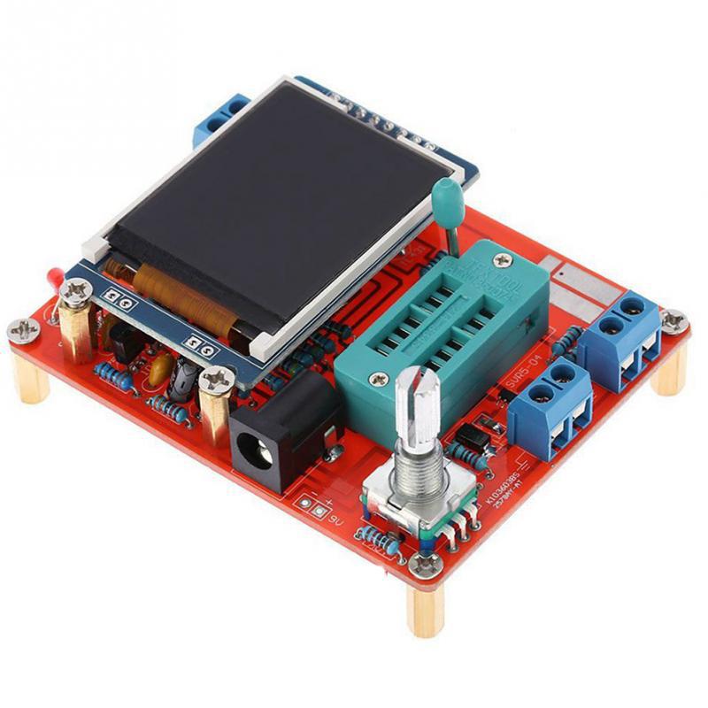


The JS-56-108 DIY Transistor Tester Kit is an educational and practical kit that users assemble themselves to create a versatile LCR/ESR meter and multi-function signal generator. This product is a perfect blend of a soldering practice module and a valuable diagnostic tool for electronics work.
Long Product Description
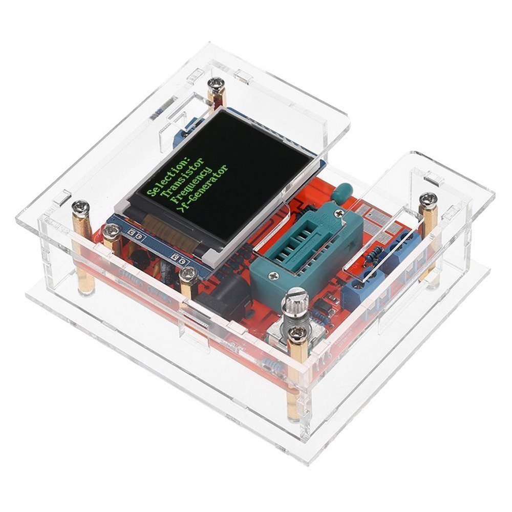
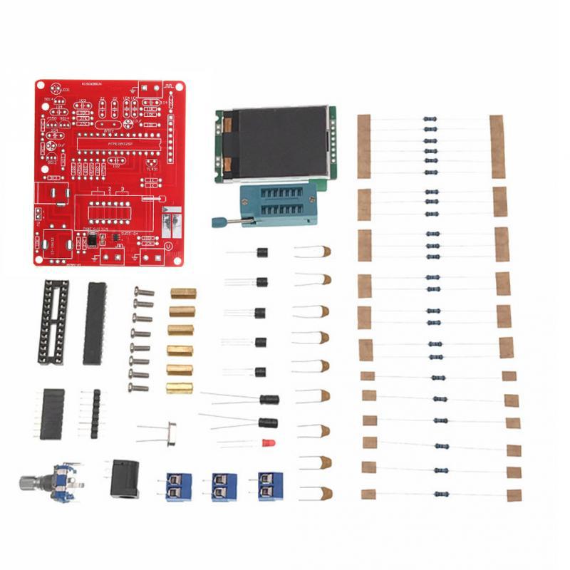
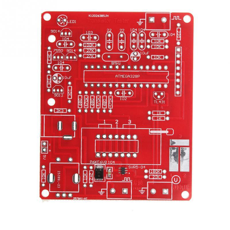
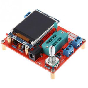
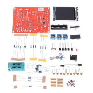
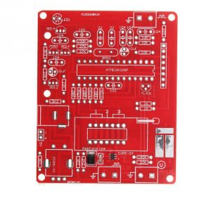
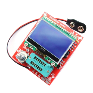
The JS-56-108 DIY Kit is more than just a component tester; it is a comprehensive learning platform and a highly functional piece of bench equipment once assembled. This kit requires the user to solder all components onto the printed circuit board (PCB), providing excellent hands-on experience for beginners or students while resulting in a powerful, self-contained tester. Utilizing an ATmega-series microcontroller, the finished device automatically identifies various components (transistors, diodes, capacitors, resistors, inductors, SCRs) and displays their characteristics on a clear graphical LCD. A unique selling point is the integrated signal generator function, which outputs precise PWM (Pulse Width Modulation) and square wave signals, essential for testing digital logic or driving motors and LEDs.
Key Features
- Automatic Component Identification: Detects and distinguishes between NPN/PNP bipolar transistors, N-channel and P-channel MOSFETs, JFETs, diodes, double diodes, and thyristors.
- Detailed Parameter Display: Provides crucial information like transistor current amplification factor (hFE), base-emitter conduction voltage (Uf), MOSFET threshold voltage, and gate capacitance.
- ESR Measurement: Automatically detects and displays the Equivalent Series Resistance (ESR) for capacitors above 0.09uF with 0.01 ohm resolution.
- Integrated Signal Generator: Includes a built-in function to generate PWM (Pulse Width Modulation) signals and square waves, useful for various testing scenarios.
- Soldering Practice Module: Provided as a kit, it offers a hands-on opportunity to learn and practice electronic assembly and soldering skills.