PCA9685 16-Channel PWM Servo Motor Controller Board (Pre-Soldered Pins)

SKU: FA2004-1
Driver Chip

PCA9685

Logic Voltage (VCC)

2.3V to 5.5V

External Power (V+)

Up to 6V (typically 5V for servos)

Communication Interface

I²C (Fast-mode Plus, up to 1 MHz)

Channels

16 independent PWM channels

Resolution

12-bit (4096 steps)

Frequency Range

24 Hz to 1526 Hz (typical default 200 Hz)

Output Current per Channel

25 mA (sink), 10 mA (source) at 5V

Max Addressable Modules

62 (via A0-A5 pins)

Dimensions

Approx. 62.5mm x 25.4mm x 3mm (board only)

Operating Temperature

-40°C to 85°C

Description
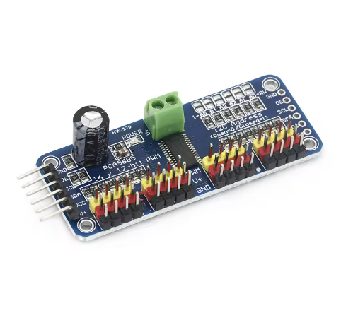
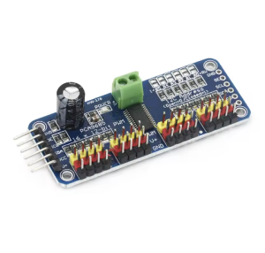
The PCA9685 16-Channel PWM Servo Motor Controller Board is a versatile and powerful solution for projects requiring multiple PWM outputs, such as robotics, automation, or advanced lighting systems. Based on the NXP PCA9685 controller chip, this board communicates via the I²C interface, requiring only two data pins (SDA and SCL) from your microcontroller (like Arduino, Raspberry Pi, or ESP32) to manage all 16 channels simultaneously. A key feature is the integrated clock, which allows the connected devices to operate without continuously tying up your microcontroller’s processing power.
Each of the 16 channels offers a precise 12-bit resolution (4096 steps), allowing for very smooth and accurate control of servo positions or LED brightness. The PWM frequency is adjustable from approximately 24 Hz to 1526 Hz, making it suitable for both standard 50-60 Hz servos and higher-frequency LED dimming applications.
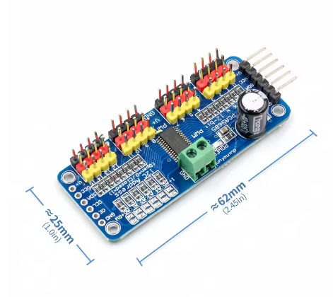
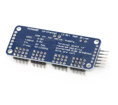
The board is designed for flexibility and expandability. It features a chainable design with address selection pins, allowing up to 62 boards to be connected on a single I²C bus, controlling a potential total of 992 outputs. The board includes a terminal block for an external power supply (up to 6V, typically 5V for most servos) to power the attached devices, ensuring that high-current loads do not strain the host microcontroller’s power supply. The pre-soldered pins offer a convenient, plug-and-play experience, ideal for both hobbyists and professionals.
Features
  • 16 Independent Channels: Provides 16 dedicated PWM outputs, each with its own independent ON/OFF time and duty cycle control.
  • I²C Communication: Uses only two I/O pins (SDA, SCL) to control all 16 channels, freeing up valuable microcontroller pins.
  • Integrated Clock: Built-in 25 MHz internal oscillator means no continuous signal is needed from the host microcontroller, reducing overhead.
  • High Resolution: Offers 12-bit (4096 steps) resolution for each channel for precise control.
  • Adjustable Frequency: Programmable PWM frequency range from 24 Hz to 1526 Hz.
  • Wide Compatibility: 5V compliant inputs/outputs allow control from 3.3V microcontrollers (like Raspberry Pi) while safely driving up to 6V outputs for LEDs or servos.
  • Chainable Design: Up to 62 modules can be connected in series on a single I²C bus, offering massive scalability for large projects (up to 992 outputs).
  • External Power Input: Features a terminal block for a separate external power source (e.g., 5-6V for servos) to handle high current requirements with reverse polarity protection.
  • Pre-Soldered Pins: Comes with all necessary header pins pre-soldered for ease of use and quick setup.
  • Output Protection: Each PWM output line has a 220-ohm series resistor for protection and ease of driving LEDs.
Usage
The PCA9685 board is designed to be easily integrated into microcontroller-based projects using the I²C protocol.
  1. Connections:
    • Connect the VCC pin to your microcontroller’s logic power supply (3.3V or 5V).
    • Connect the GND pin to the common ground of your system and external power supply.
    • Connect the SDA and SCL pins to your microcontroller’s I²C data and clock lines, respectively.
    • Connect a separate, regulated power supply (typically 5-6V for servos) to the V+ terminal block (or pin) to power the attached servos or LEDs.
  2. Configuration:
    • The board has a default I²C address of 0x40. For multiple boards, use the address selection solder pads (A0-A5) to assign unique addresses to each board (up to 62 total).
  3. Programming:
    • Use a compatible library for your chosen platform (e.g., Adafruit PWM Servo Driver library for Arduino/CircuitPython, or relevant libraries for Raspberry Pi or ESP32).
    • Initialize the library and set the desired PWM frequency (50-60 Hz is standard for servos).
    • Use the library functions to set the pulse width (or angle, depending on the library) for each channel to control the connected device.
Q: What is the primary use of the PCA9685 board?

The board is primarily used to control up to 16 servos or LEDs simultaneously when the main microcontroller has insufficient PWM output pins.

Q: Can I power the servos directly from my Arduino's 5V pin?

It is generally not recommended to power multiple servos directly from your microcontroller’s 5V pin, as servos draw significant current and can cause power issues or brownouts. Use a separate, dedicated external power supply connected to the V+ pin

Q: What is the PWM resolution, and what does it mean?

The PCA9685 offers 12-bit resolution, which provides 4096 individual steps of control for each channel. This allows for very fine and precise control over the position of a servo or the brightness of an LED

Q: Can I control both LEDs and servos at the same time with this board?

Yes, you can. However, all outputs on the PCA9685 share the same PWM frequency. Servos typically require a frequency of around 50-60 Hz, while LEDs can benefit from higher frequencies (e.g., 1000 Hz) to avoid flicker. You must set the board to a single, consistent frequency for all channels

Q: How many of these boards can I use in a single project?

The board has 6 address selection pins, allowing you to chain up to 62 modules on the same I²C bus, controlling a maximum of 992 PWM outputs. Each board must be assigned a unique I²C address via the solder pads