Product Overview
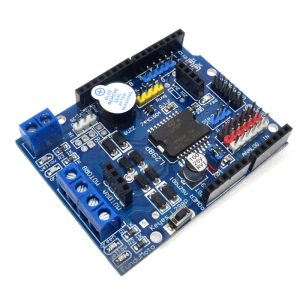
The High-Power L298P Motor Shield is a feature-rich expansion module designed to transform your Arduino (or compatible microcontroller) into a powerful motor control workstation. Unlike discrete motor driver modules, this shield adopts a stackable design that plugs directly onto your Arduino Uno or Mega board, eliminating the need for complex breadboard wiring and creating a compact, integrated control system .
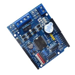
At its core is the ST L298P motor driver IC—a dual full-bridge driver capable of handling high voltage and high current. This shield can independently control the speed and direction of two DC motors or drive one bipolar stepper motor with precision. With a continuous output current of 2A per channel (peaks up to 3A) and support for motor supply voltages up to 35V, it is suitable for a wide range of robotics, CNC, and automation projects .
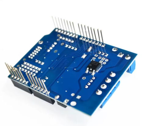
The L298P represents an upgrade over the traditional L298N, featuring an integrated heat sink that allows for a lower profile, making the shield stackable with other shields. Additional enhancements include 8 LED indicators for real-time status monitoring (power, direction, speed) and a convenient power switch for easy debugging . Advanced features like current sensing allow your projects to detect motor stalls, measure load, and implement closed-loop control algorithms .
Key Features
-
Stackable Arduino Shield Design: Plugs directly onto Arduino Uno or Mega boards. The low-profile integrated heat sink allows for stacking with other shields, saving space and simplifying assembly .
-
Dual H-Bridge Driver: Based on the STMicroelectronics L298P IC, providing two independent H-bridges for bidirectional control of two DC motors or one bipolar stepper motor .
-
High Output Current: Delivers a continuous 2A current per channel (3A peak), capable of driving a wide variety of hobby and industrial-grade motors .
-
Wide Motor Supply Voltage: Accepts motor power from 4.8V to 35V (via external power terminals), offering flexibility for different motor types and battery configurations .
-
Integrated 5V Logic Regulator: An onboard regulator provides logic power (5V) to the shield and can also power the Arduino board when the motor supply is between 7V and 12V (jumper selectable) .
-
PWM Speed Control: Supports both conventional PWM and advanced PLL (Phase-Locked Loop) speed control modes for smooth, efficient motor speed regulation .
-
Onboard Current Sensing: Features analog current sensing outputs (typically A0 and A1). The shield outputs a voltage proportional to the motor current (approx. 1.65V per Amp or 3.3V at 2A), enabling torque control and stall detection .
-
Brake Function: Includes dedicated brake pins that rapidly short the motor terminals for quick, controlled stopping .
-
8 LED Indicators: Provides visual feedback with LEDs for power, reset, motor direction, and PWM activity, simplifying troubleshooting .
-
On/Off Power Switch: A built-in slide switch allows you to cut motor power without unplugging cables, which is invaluable during programming and debugging .
-
Expandable I/O: Brings out additional digital and analog pins via 2.54mm headers, allowing you to connect sensors and other peripherals without sacrificing your Arduino’s I/O .
Technical Specifications
Pinout & Interface Guide
Power Section
-
External Power Terminals (PWRIN +/-): Main screw terminals for motor power. Connect your battery or power supply (4.8V-35V) here. External power is strongly recommended for reliable motor operation .
-
VIN Jumper: A jumper on the back of the shield selects the power source for the motors and logic.
-
Jumper ON: Motor power is taken from the Arduino’s VIN pin (useful when Arduino is powered via its barrel jack) .
-
Jumper OFF: Motor power is taken from the external PWRIN terminals. This is the preferred configuration for high-current motors .
-
Power Switch: A slide switch (often labeled “ON/OFF”) controls the main motor power, allowing you to enable or disable the motors while keeping the Arduino logic powered .
Motor Outputs
-
Motor A Terminals (OUT1, OUT2): Screw terminals for connecting your first DC motor (Motor A) or one coil of a stepper motor.
-
Motor B Terminals (OUT3, OUT4): Screw terminals for your second DC motor (Motor B) or the second coil of a stepper motor.
Control Pins (Arduino Interface)
The shield uses specific Arduino pins to control the motors :
(Note: Pin assignments may vary slightly between manufacturers; always verify with the silkscreen on your specific shield.)
LED Indicators
-
Power LED: Indicates that the shield is receiving logic power.
-
Direction LEDs (4): One set for Motor A and one for Motor B. They illuminate based on the state of the direction pins (D4, D7), showing which direction the motors are commanded to turn .
-
PWM LEDs (4): One set for Motor A and one for Motor B. Their brightness varies with the PWM duty cycle, giving a visual indication of motor speed .
Usage Guide
Important Pre-Operation Requirements
Power Supply Considerations:
-
Use an External Power Supply: The motors connected to this shield can draw significant current. Powering them through the Arduino’s USB or 5V pin is not recommended and may damage your Arduino. Always use an external power source connected to the PWRIN terminals .
-
Power Rating: Ensure your external power supply is rated for at least the total current draw of your motors (plus a 20-30% safety margin). For two motors drawing 2A each, use a 5A or higher power supply.
-
Voltage Selection: Set the power switch to the “ON” position after uploading your code to enable the motors .
Wiring Guide
-
Mount the Shield: Carefully align the shield’s pins with the headers on your Arduino Uno or Mega and press firmly to seat it.
-
Set Power Jumper: Decide on your power source.
-
Connect External Power: Connect your external power supply (battery or adapter) to the PWRIN screw terminals, observing correct polarity (+ to +, – to -). Do not power the shield yet.
-
Connect Motors: Connect your DC motors to the Motor A and Motor B screw terminals. For a single motor, polarity determines initial direction; swap the wires if you need to reverse it.
-
Power Up: First, connect your Arduino to your computer via USB for programming. Then, connect/turn on your external motor power supply. The shield’s power LED should illuminate.
Control Logic Table (DC Motor Operation)
Current Sensing Application
The shield provides analog feedback of the current drawn by each motor .
-
Read the Value: Use analogRead(A0) for Motor A and analogRead(A1) for Motor B.
-
Interpret the Value: On the official Arduino Motor Shield, the output is calibrated to be 3.3V when the channel current is 2A . This means:
This feedback can be used to:
-
Detect if a motor has stalled (sudden current spike).
-
Monitor the mechanical load on your robot.
-
Implement closed-loop torque control.
Example Arduino Code (Basic Motor Control)
void setup() {
pinMode(4, OUTPUT);
pinMode(5, OUTPUT);
pinMode(7, OUTPUT);
pinMode(6, OUTPUT);
pinMode(9, OUTPUT);
pinMode(8, OUTPUT);
digitalWrite(9, LOW);
digitalWrite(8, LOW);
}
void loop() {
digitalWrite(4, HIGH);
analogWrite(5, 255);
digitalWrite(7, LOW);
analogWrite(6, 127);
delay(2000);
analogWrite(5, 0);
analogWrite(6, 0);
delay(1000);
digitalWrite(4, LOW);
analogWrite(5, 127);
digitalWrite(7, HIGH);
analogWrite(6, 255);
delay(2000);
analogWrite(5, 0);
analogWrite(6, 0);
delay(1000);
}
Q: What is the difference between this L298P Motor Shield and a standard L298N module?
There are several key differences:
-
Form Factor: The L298P is a shield designed to plug directly onto an Arduino, while L298N is typically a standalone module requiring wiring .
-
IC Package: The L298P uses a PowerSO20 package with an integrated heat sink, making it lower profile and stackable. The L298N is a Multiwatt package with a separate, bulky heatsink .
-
Features: The L298P Shield often includes current sensing, brake control, and LEDs, which are not standard on basic L298N modules
Q: What types of motors can I use with this shield?
This shield can control:
-
Two brushed DC motors (most common application)
-
One bipolar stepper motor (using both channels)
-
It is not suitable for brushless DC motors (BLDC) or servo motors.
Q: Can I use this shield with an Arduino Mega?
Yes. The shield is designed to be compatible with both Arduino Uno (and similar form factors) and Arduino Mega boards. The pin alignment accommodates the different layouts
Q: Can I stack other shields on top of this one?
Yes, usually. Because the L298P uses an integrated heat sink, the shield maintains a low profile. However, stacking depends on the shields above not using the pins occupied by this shield (D4-D9, A0-A1) and having compatible stacking headers
Q: How do I power this shield correctly?
For reliable operation, follow these steps:
-
Connect a suitable external power supply (e.g., battery or adapter) to the PWRIN screw terminals .
-
Ensure the VIN jumper on the back of the shield is OPEN (cut or removed) to separate the motor power from the Arduino’s VIN line .
-
Connect your Arduino to your computer via USB for programming.
-
Turn on the external power supply, then flip the shield’s power switch to ON. The power LED should light up
Q: What happens if I use the shield without an external power supply?
The motors will likely run very weakly or not at all. Attempting to draw motor current through the Arduino’s USB or 5V regulator can overload and potentially damage your Arduino or computer’s USB port
Q: What is the maximum voltage I can use?
The motor supply voltage (VS) can range from 4.8V to 35V when using the external PWRIN terminals . Exceeding 35V can permanently damage the shield.
Q: My motors run weakly or stop under load. What's wrong?
This is almost always a power issue:
-
Power Supply Current: Your external power supply may not be able to deliver enough current. Check its rating against your motor’s stall current.
-
Voltage Drop: Thin wires or a weak battery can cause the voltage to sag under load.
-
Power Switch: Ensure the shield’s power switch is in the ON position
Q: The shield gets hot. Is this normal?
The L298P will generate heat, especially when driving motors near the 2A limit. The integrated heat sink is designed to dissipate this heat. It is normal for it to become warm to the touch. If it becomes too hot to touch (>70°C), you may be exceeding the current rating or there may be a short circuit. Reduce the load or improve airflow.
Q: How do I use the brake function?
The brake pins (D8 for Motor B, D9 for Motor A) are active HIGH. Setting the brake pin to HIGH while keeping the PWM pin LOW will rapidly stop the motor by shorting its terminals . Avoid switching directly from forward to reverse without a brief brake or stop period to prevent current spikes.
Q: The current sensing readings don't seem accurate. Why?
The current sensing output is a rough analog representation, not a precision measurement. It is calibrated to output 3.3V at the maximum rated current (2A) . This is excellent for relative measurements (e.g., “is the motor stalled?”) but may not be accurate enough for scientific instrumentation.
Q: The motor only runs in one direction.
Check your code to ensure you are setting the direction pins (D4 for Motor A, D7 for Motor B) to opposite states for forward and reverse. Also, verify the wiring and that the brake pins are not being accidentally held HIGH.
Q: What do the extra LEDs indicate?
The shield typically includes:
-
Direction LEDs: These light up to show which direction the motor is commanded to turn (based on the state of D4 and D7) .
-
PWM/Speed LEDs: These LEDs vary in brightness with the PWM signal, giving a visual indication of motor speed .
Q: Can I use pins D4-D7 for other things if I'm not using the motor shield?
No. When the shield is stacked, those pins are physically connected to the shield’s circuitry. You cannot use them for other purposes unless the shield is removed or you have modified it to isolate those pins.