Product Overview
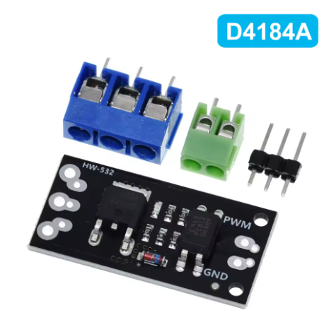
The AOD4184 MOSFET Isolation Module is a high-performance, solid-state switching solution designed to replace mechanical relays in modern electronics. Built around the advanced AOD4184 N-Channel MOSFET from Alpha & Omega Semiconductor, this module combines exceptional power efficiency with robust opto-isolation to create a safe, reliable, and fast-switching interface between your low-voltage microcontroller and high-power DC loads .
The AOD4184 MOSFET utilizes advanced trench technology to achieve an extremely low on-resistance of just 7mΩ (typical) at VGS = 10V . This ultra-low resistance ensures minimal power loss and heat generation, even when switching currents up to 50A continuously . The result is a highly efficient switching solution that outperforms traditional relays in virtually every metric.
A key feature of this module is its built-in optocoupler isolation (typically using a PC817 or similar), which creates a complete electrical barrier between the control signal (your microcontroller) and the high-power load circuit . This protects your sensitive and expensive Arduino, ESP32, Raspberry Pi, or PLC from dangerous voltage spikes, back-EMF from motors, and ground loop interference.
This module serves as the ideal replacement for mechanical relays in applications where:
-
High switching speed is required (PWM control for dimming or speed regulation)
-
Silent operation is necessary (no mechanical clicking)
-
Long-term reliability is critical (no contacts to wear out or weld)
-
Low power consumption is essential (battery-powered devices)
-
Compact size is a constraint
Common applications include DC motor speed control, high-power LED dimming, solenoid valve actuation, pump control, and general-purpose high-side or low-side DC switching in industrial automation, robotics, and automotive systems .
Key Features
-
High-Performance AOD4184 MOSFET: Based on the advanced AOD4184 N-Channel MOSFET from Alpha & Omega Semiconductor, featuring trench technology for exceptionally low on-resistance and high efficiency .
-
Ultra-Low On-Resistance: Delivers an incredibly low RDS(on) of 7mΩ (typical) at VGS = 10V , and less than 9.5mΩ at VGS = 4.5V . This minimizes power loss and heat generation, even at high currents.
-
High Current Capacity: Capable of handling continuous drain currents up to 50A (at TC=25°C) . Pulsed drain current can reach up to 120A .
-
Robust Voltage Handling: Supports drain-source voltages up to 40V , making it suitable for 12V, 24V, and 36V DC systems.
-
Opto-Isolated Control Input: Features an optocoupler that provides galvanic isolation between the control signal and the power circuit . This critical feature:
-
Protects microcontrollers from back-EMF and voltage spikes
-
Eliminates ground loop interference
-
Enhances noise immunity in industrial environments
-
Wide Logic Voltage Compatibility: Accepts control signals from 3V to 5V (and potentially higher), making it directly compatible with both 3.3V microcontrollers (ESP32, Raspberry Pi Pico) and 5V systems (Arduino) .
-
PWM Compatible for Analog Control: Fully supports high-speed PWM signals, enabling smooth and efficient speed control of DC motors or stepless dimming of high-power LED lighting .
-
Simple Active-HIGH Logic: Intuitive control—apply a HIGH logic signal (or PWM) to turn the MOSFET ON and connect the load; apply LOW to turn it OFF .
-
Compact and Modular Design: Small footprint of just 23mm x 16mm with two 2mm diameter mounting holes (8mm spacing), allowing for easy integration into tight spaces .
-
Flexible Connection Options: Features solder pads for both pin headers and screw terminals, allowing you to configure the module for breadboard prototyping or permanent installations .
-
Excellent Thermal Performance: With an operating temperature range of -55°C to +175°C , this module is built to withstand demanding environmental conditions.
-
100% UIS and Rg Tested: The AOD4184 MOSFET undergoes rigorous testing, including 100% UIS (Unclamped Inductive Switching) and 100% Rg (Gate Resistance) testing, ensuring reliability in demanding applications .
Technical Specifications
Pinout & Interface Guide
The module is clearly divided into a low-voltage control side and a high-voltage power side.
Control Side (Signal Input)
-
SIG / PWM (Signal): The control input. Apply a HIGH logic signal (3V-5V) to turn the MOSFET ON. Apply LOW (0V) to turn it OFF . Sending a PWM signal enables speed or brightness control .
-
GND (Ground): Common ground for the control side. Connect to a GND pin on your microcontroller. This ground is electrically isolated from the load ground .
Power Side (Load Connections)
-
V+ (Power Input): The positive input for your external DC power supply (up to 40V). Connect the positive lead from your battery or power supply here .
-
V- (Load Output): The switched output. Connect the negative wire of your load (motor, LED strip, solenoid, etc.) to this terminal. The MOSFET acts as a switch between this terminal and the power supply ground .
Important Wiring Note: This module is typically configured for low-side switching. The positive wire of your load must be connected directly to the positive (+) terminal of your external power supply. The module switches the ground (negative) side of the circuit .
Usage Guide
Important Safety Warnings
-
DC ONLY: This module is designed strictly for DC circuits . Never connect AC mains power (e.g., household 110V/220V AC) to this module. It will be destroyed instantly and poses a serious safety hazard.
-
Inductive Loads Require a Flyback Diode: When controlling inductive loads like motors, solenoids, or relays, you MUST add an external flyback (snubber) diode across the load’s terminals (cathode/banded end to load positive, anode to load negative). The module does not include this diode, and switching inductive loads without it will eventually damage the MOSFET.
-
Thermal Management: While the AOD4184 MOSFET is rated for very high peak currents (50A+), the small PCB has minimal heatsinking capability . For continuous operation above 5-10A, provide active cooling (a fan) or attach a small heatsink to the MOSFET.
-
Voltage Limits: Do not exceed the maximum drain-source voltage of 40V . Exceeding this rating can cause catastrophic failure.
-
Current Limits: The maximum continuous current rating of 50A applies when the device is properly heatsinked with a case temperature (TC) of 25°C . In practical use on this small module, the current is limited by the PCB traces and ambient cooling to significantly lower values.
Wiring Guide (Controlling a 12V DC Motor with Arduino)
Basic Arduino Example Code
This code demonstrates simple on/off control and PWM speed control.
int mosfetPin = 9;
int speed = 0;
void setup() {
pinMode(mosfetPin, OUTPUT);
}
void loop() {
digitalWrite(mosfetPin, HIGH);
delay(2000);
digitalWrite(mosfetPin, LOW);
delay(2000);
for (speed = 0; speed <= 255; speed++) {
analogWrite(mosfetPin, speed);
delay(10);
}
for (speed = 255; speed >= 0; speed--) {
analogWrite(mosfetPin, speed);
delay(10);
}
delay(1000);
}
Q: What is the advantage of this module over a mechanical relay?
This MOSFET module offers several key advantages over mechanical relays :
-
High-Speed Switching: Can switch on/off thousands of times per second, enabling PWM for speed control and dimming.
-
Silent Operation: No audible “click” sound during switching.
-
Solid-State Reliability: No mechanical contacts to wear out, pit, or weld over time.
-
Low Power Consumption: Requires very little current to operate, ideal for battery-powered applications.
-
No Contact Bounce: Clean switching without the electrical noise of relay contact bounce.
Q: What types of loads can I control with this module?
You can control various DC loads up to 40V, including :
-
DC motors (for speed control via PWM)
-
High-power LED strips and lighting (for dimming)
-
Solenoid valves and relays
-
DC pumps and fans
-
Other DC-powered actuators and resistive loads
Q: Can this module control AC loads (like a household appliance)?
No, absolutely not. This module is strictly for DC circuits only . The AOD4184 is an N-Channel MOSFET designed for DC switching and cannot block AC current.
Q: Can I use this module with a 3.3V controller like a Raspberry Pi or ESP32?
Yes. The control input is compatible with 3.3V logic levels . The AOD4184 MOSFET has a low gate threshold voltage and can be driven directly by 3.3V signals.
Q: What does "opto-isolated" mean and why is it important?
Optical isolation means there is no direct electrical connection between the control side (your microcontroller) and the power side (the load). Instead, they communicate via light through an optocoupler . This protects your sensitive and expensive microcontroller from dangerous voltage spikes, back-EMF from motors, and ground loop interference.
Q: What is the real-world current limit for this module?
While the AOD4184 MOSFET itself is rated for 50A continuous current (at TC=25°C) , the practical, continuous current is limited by the small PCB’s ability to dissipate heat. For reliable, continuous operation on this module without additional heatsinking, it’s wise to stay within 5-10A. For short bursts or with a good heatsink attached, you can push higher
Q: Do I need a flyback diode for my motor?
Yes, absolutely required. The module does not include one. When switching any inductive load (motor, solenoid, pump), the collapse of the magnetic field generates a high-voltage spike that can instantly destroy the MOSFET. An external flyback diode (e.g., 1N4007 or 1N4148) connected across the load terminals is essential for long-term reliability
Q: The module gets hot. Is this normal?
Some heat is normal when switching high currents. The AOD4184 has a very low on-resistance (7mΩ) , so at 10A it will dissipate about 0.7 watts (P = I²R = 10² × 0.007 = 0.7W). This should be barely warm. At 20A, dissipation rises to 2.8 watts, which will require a heatsink. If the MOSFET is too hot to touch (>60°C), you need better cooling or to reduce the current.
Q: Why are there two different current ratings (50A and 6.5A)?
The 50A rating is the absolute maximum current the MOSFET silicon can handle when the case temperature (TC) is held at 25°C with perfect cooling . The 6.5A rating is the more realistic maximum current the device can handle when mounted on a standard PCB in room temperature air (TA=25°C) without additional heatsinking . This accounts for the thermal limitations of the PCB and ambient environment.
Q: My load doesn't turn on, even though the control signal is HIGH.
Follow this checklist:
-
Check Wiring: Remember, this is a low-side switch. Ensure the load’s positive wire goes directly to the power supply + terminal, and the load’s negative wire goes to the module’s V- terminal.
-
Check Power Supply: Verify your external power supply is on and providing the correct voltage (up to 40V).
-
Check Signal Ground: Ensure the control-side GND is connected to your microcontroller’s ground.
-
Check Voltage: Measure the voltage at the SIG pin with your microcontroller; it should be HIGH (3.3V/5V).
Q: The load stays on even when the control signal is set to LOW.
This indicates the MOSFET is not fully turning off. Ensure your microcontroller pin is configured as an OUTPUT and is being driven firmly to LOW (0V) . A failing optocoupler or a shorted MOSFET could also cause this.
Q: My PWM control is jerky or the motor makes a loud noise.
This is often a frequency issue. Try lowering the PWM frequency in your code. Experiment with values from a few hundred Hz to a few kHz for optimal performance with your specific motor.
Q: Is the signal ground and load ground the same?
No. Due to the opto-isolation, the signal ground (from your microcontroller) and the load power ground are electrically isolated and are not connected on the module . Do not connect them together externally.