Product Overview
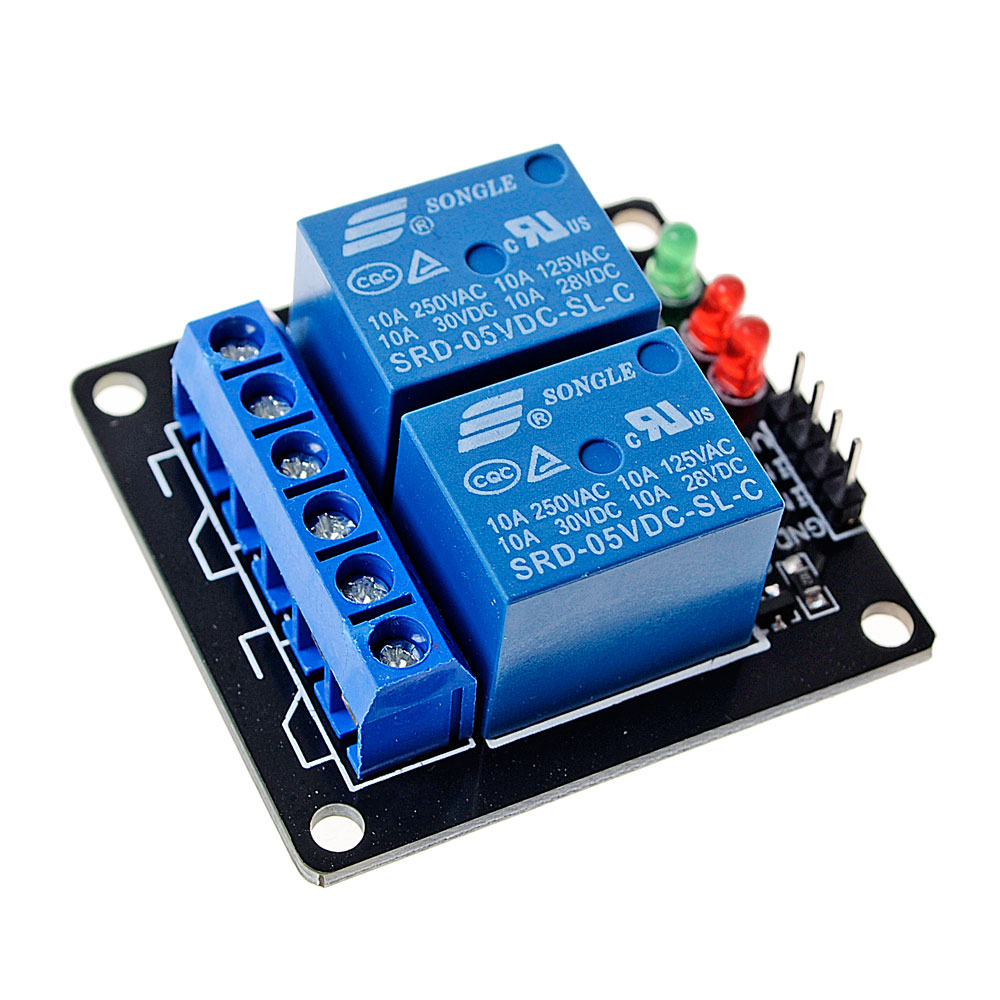
The 5V 2-Way Electromagnetic Relay Module is a simple, cost-effective switching solution designed to control two independent high-power AC or DC loads directly from a 5V logic system. Unlike more complex relay modules that incorporate optocoupler isolation, this module uses a direct transistor driver circuit (typically NPN transistors such as 2N2222, BC547, or S8050) to activate each relay coil . This design offers a lower cost and simpler circuit, making it ideal for hobbyist projects, educational use, and applications where isolation is not critical.
This dual-channel module allows you to control two separate devices independently from your microcontroller. With each relay rated for 10A at 250V AC or 10A at 30V DC, it can handle lights, fans, motors, pumps, solenoids, and other household or industrial appliances . Onboard status LEDs provide visual confirmation when each relay is activated, simplifying operation monitoring and troubleshooting.
Designed with a low-level trigger, the relays activate when the control pins are pulled LOW (0V) and deactivate when pulled HIGH (5V) . This active-LOW behavior provides a degree of safety—the relays remain off during power-up or if the control signal is lost, preventing accidental activation of connected devices.
Important Note: This module does not include optocoupler isolation. The control circuit and the high-voltage load share a common ground path . Exercise caution when wiring high-voltage loads and ensure proper insulation and clearance for safety .
Key Features
-
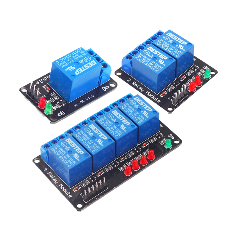
Dual Independent Channels: Two separate relay channels allow independent control of two different loads from a single module .
-
Low-Level Trigger (Active LOW): Each relay activates when its corresponding IN pin is pulled LOW (0V) and deactivates when HIGH (5V). This ensures the relays remain off during power-up .
-
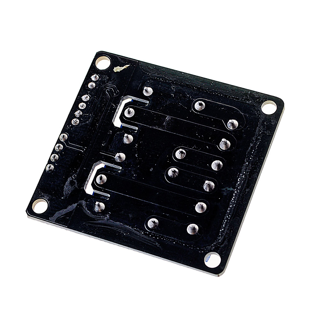
Direct Transistor Drive: Uses simple NPN transistors (such as 2N2222, BC547, or S8050) to drive each relay coil, eliminating the need for optocoupler components .
-
10A High Switching Capacity: Each relay contacts rated for 10A at 250V AC or 10A at 30V DC, suitable for controlling lights, fans, motors, pumps, and industrial equipment .
-
SPDT Contact Configuration: Each channel provides Common (COM), Normally Open (NO), and Normally Closed (NC) terminals for maximum wiring flexibility—use NO for OFF-by-default operation or NC for ON-by-default operation .
-
Status Indicator LEDs: Onboard LEDs for each channel illuminate when the corresponding relay is activated (IN pin LOW), providing clear visual feedback .
-
5V Logic Compatibility: Designed for 5V microcontrollers like Arduino, STM32, and 5V logic systems, with a control signal range of 0V–5V .
-
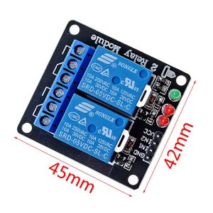
Compact and Lightweight: Small PCB footprint with mounting holes for easy integration into breadboards, enclosures, or control panels .
-
Simple 5-Pin Control Interface: Standard 2.54mm pitch header (VCC, GND, IN1, IN2) allows direct connection to microcontrollers, sensors, or manual switches .
Technical Specifications
Pinout & Interface Guide
Input Side (Control Interface)
Output Side (Load Terminals) – Channel 1
Output Side (Load Terminals) – Channel 2
Status LEDs
Usage Guide
Wiring Instructions
IMPORTANT: Always disconnect mains power before wiring high-voltage loads.
Basic Connection (Control Side)
Load Connection (AC Example for One Channel)
-
Connect the Live (L) wire from your AC source to the COM terminal
-
Connect the load (lamp, fan, motor) to the NO terminal for OFF-by-default operation
-
Connect the load’s Neutral (N) wire directly to the AC source neutral
Load Connection (DC Example for One Channel)
-
Connect the positive (+) supply to the COM terminal
-
Connect the load’s positive wire to the NO terminal
-
Connect the load’s negative wire directly to the power supply ground
Control Logic
Since this module is low-level triggered, the relay behavior is as follows:
Example Arduino Code
const int relay1Pin = 7;
const int relay2Pin = 8;
void setup() {
pinMode(relay1Pin, OUTPUT);
pinMode(relay2Pin, OUTPUT);
digitalWrite(relay1Pin, HIGH);
digitalWrite(relay2Pin, HIGH);
}
void loop() {
digitalWrite(relay1Pin, LOW);
delay(3000);
digitalWrite(relay1Pin, HIGH);
delay(1000);
digitalWrite(relay2Pin, LOW);
delay(3000);
digitalWrite(relay2Pin, HIGH);
delay(1000);
digitalWrite(relay1Pin, LOW);
digitalWrite(relay2Pin, LOW);
delay(2000);
digitalWrite(relay1Pin, HIGH);
digitalWrite(relay2Pin, HIGH);
delay(2000);
}
Important Considerations
-
Power Supply: The module requires a stable 5V DC supply capable of providing at least 200mA (80mA per relay when both active). The Arduino’s 5V pin can typically supply this for a single module .
-
No Optocoupler Isolation: This module does not provide electrical isolation between the control circuit and the high-voltage load. The control and load circuits share a common ground path. For applications requiring isolation, consider an optocoupler-isolated relay module .
-
Inductive Loads: For motors, pumps, or solenoids, add a flyback diode across each load to protect the relay contacts from voltage spikes . The module typically includes flyback diodes across each relay coil, but external diodes across inductive loads are recommended .
-
Default State: The low-level trigger design means the relays stay OFF when the IN pins are HIGH or unconfigured, preventing unwanted activation during power-up .
-
Current Limitations: If using multiple relay modules, consider using an external 5V power supply to avoid overloading your microcontroller’s regulator .
Q: What is the difference between this module and an optocoupler-isolated relay module?
This module uses direct transistor drivers to activate the relay coils, without optocoupler isolation. Optocoupler-isolated modules have an optical barrier between the control circuit and the load, providing electrical isolation. This module is more cost-effective but does not provide isolation between your microcontroller and the high-voltage load .
Q: What is the advantage of low-level trigger?
Low-level trigger means the relay activates when the IN pin is pulled LOW (0V). This is a safety feature—the relay remains off during power-up or if the control signal is lost, preventing accidental activation of connected devices .
Q: Can I use this module with a 3.3V microcontroller like ESP32 or Raspberry Pi Pico?
Yes. The module is designed for 5V logic, but a 3.3V HIGH signal (3.3V) is typically sufficient to deactivate the relay. The LOW signal (0V) works regardless of logic voltage. For reliable operation, ensure the 3.3V HIGH signal is above the transistor’s turn-off threshold (typically around 0.7V–1.5V)
Q: What is the maximum load each relay can handle?
Each relay contacts are rated for 10A at 250V AC or 10A at 30V DC . For inductive loads like motors, it is recommended to derate to 5A–7A to account for startup surges.
Q: What is the difference between NO and NC terminals?
-
NO (Normally Open): The circuit is open when the relay is OFF. When the relay activates, it closes. Use NO for devices that should be OFF by default .
-
NC (Normally Closed): The circuit is closed when the relay is OFF. When the relay activates, it opens. Use NC for devices that should be ON by default .
Q: What power supply do I need for this module?
The module requires a stable 5V DC power supply capable of providing at least 200mA (80mA per relay when both active). If powering from an Arduino’s 5V pin, it can typically supply this for a single module .
Q: The relays click but my loads don't turn on. What's wrong?
This indicates the relays are activating but the load circuits are incomplete. Check:
-
Each load is correctly wired between COM and NO (or COM and NC)
-
Each load’s neutral/ground is connected correctly
-
The loads themselves are functional
-
The load currents do not exceed the relay’s 10A rating
Q: The relays click when I power on my microcontroller. Why?
During power-up, microcontroller pins may briefly float or be in an undefined state. With a low-level trigger module, this should not activate the relays because the pins need to be pulled LOW. Adding 10kΩ pull-up resistors on each IN pin to VCC can ensure the relays remain OFF during startup .
Q: What is the expected lifespan of these relays?
Each relay is rated for approximately 100,000 electrical operations at rated load . Actual lifespan depends on switching frequency and load type.
Q: Can I use this relay module for 220V AC applications?
Yes. The contacts are rated for 250V AC, which is suitable for 220V/240V systems. Ensure proper insulation and clearance between the control and load sides for safety . Since this module lacks optocoupler isolation, extra caution is required when wiring high-voltage loads .
Q: The relay status LEDs light up but the relays don't click. What's wrong?
If the LEDs are on but the relays don’t click, check:
-
The VCC power supply is stable at 5V
-
The power supply can provide enough current (at least 200mA)
-
The transistor drivers may be faulty
Q: Do I need flyback diodes for inductive loads?
The module typically includes flyback diodes across each relay coil to protect the transistors . However, for high-power inductive loads (motors, solenoids), adding external flyback diodes across each load terminal is recommended to protect the relay contacts .
Q: Can I use multiple relay modules with a single microcontroller?
Yes. Connect each module’s VCC and GND in parallel to the same 5V supply (ensure the supply can handle the total current), and connect each IN pin to separate digital output pins on your microcontroller.
Q: What can I build with this 2-channel 5V relay module?
Popular applications include:
-
Home automation: Control two lights, fans, or appliances independently
-
Arduino projects: Multi-device control for robotics and automation
-
Irrigation systems: Control two water valves or pumps
-
Security systems: Trigger two separate alarms or access controls
-
Motor control: Control forward/reverse for a single DC motor using two relays
-
Industrial control: PLC output expansion for two devices
Q: Can I control a single motor's direction using two relays?
Yes. Using two relays, you can create an H-bridge configuration to control forward and reverse direction of a DC motor. Connect the motor between the COM terminals, and wire the NO and NC contacts appropriately .
Q: Can I use this module without a microcontroller?
Yes. You can trigger each relay by manually connecting the IN pin to GND (to activate) or leaving it disconnected (to deactivate). This can be done with simple push buttons or toggle switches connected between each IN pin and GND .
Q: Does this module work with Raspberry Pi?
Yes. Raspberry Pi GPIO pins operate at 3.3V logic, which is compatible with this 5V module. Connect VCC to 5V (from an external supply or the Pi’s 5V pin), GND to GND, and IN pins to GPIO pins. Set pins LOW to activate relays and HIGH to deactivate .