Product Overview
The TP4056 1A Lithium Battery Charger Module (Type-C, With Protection) is a complete, low-cost charging solution designed for single-cell lithium-ion and lithium-polymer (LiPo) batteries. This compact module combines a TP4056 charger IC with a DW01 battery protection IC, offering both charging and protection functions in one tiny board .
Based on the industry-standard TP4056 chip from Top Power ASIC, this module implements a Constant Current / Constant Voltage (CC/CV) charging algorithm—the correct method for safely charging lithium batteries. It automatically delivers the maximum preset current (1A by default) until the battery reaches 4.2V, then switches to constant voltage mode, gradually reducing the current until the battery is fully charged .
The integrated DW01 protection circuit provides essential safeguards: overcharge protection, over-discharge protection (cutoff at approximately 2.5V), and overcurrent protection (3A typical) . The onboard Type-C USB port allows direct connection to modern USB chargers, while alternative solder pads provide DIY wiring flexibility.
Whether you are building portable electronics, powering an Arduino project with battery backup, maintaining 18650 cells, or creating custom power banks, this TP4056 module offers a reliable, ready-to-use charging solution at a fraction of the cost of dedicated chargers .
Key Features
-
Integrated Protection Circuit: Includes DW01 battery protection IC and FS8205 dual MOSFETs, providing overcharge, over-discharge (2.5V cutoff), overcurrent (3A), and short-circuit protection .
-
USB Type-C Input: Modern reversible connector for easy connection to standard USB chargers, power banks, or computer USB ports .
-
1A Maximum Charge Current: Default charge current of 1000mA (1A), fully adjustable by changing the programming resistor for lower current applications .
-
CC/CV Charging Algorithm: Implements proper Constant Current / Constant Voltage charging method essential for lithium battery safety and longevity .
-
Dual-Color Status Indicator: Red LED indicates charging in progress; Green LED indicates fully charged or no battery connected .
-
Protected Output Terminals: OUT+ and OUT- pads pass through the DW01 protection circuit, disconnecting the load if the battery voltage drops too low (over-discharge protection) .
-
Preset 4.2V Charge Voltage: ±1.5% accuracy ensures battery is charged to the correct full voltage without risk of overcharging .
-
Automatic Recharge: When a fully charged battery drops below 4.05V (approximately 80-90% capacity), a new charging cycle automatically begins .
-
Thermal Regulation: Automatically reduces charge current if internal die temperature exceeds safe limits, protecting the chip during high-current charging .
Technical Specifications
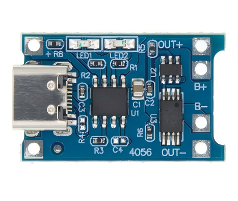
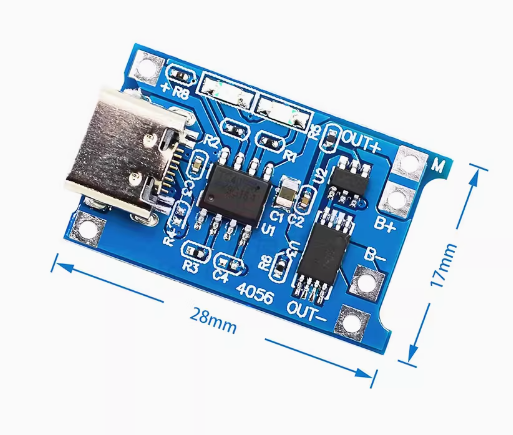
Pinout & Interface Guide
The TP4056 board is clearly labeled with connection points :
Input Side (Power Source)
Battery Connection (Charging Output)
Load Connection (Protected Output)
Status LEDs
Note: When no battery is connected, the red LED may flash while the green LED stays on.
Usage Guide
Basic Wiring Instructions
IMPORTANT: This module has NO reverse polarity protection. Connecting the battery backward will destroy the chip . Always double-check polarity before connecting.
-
Connect Power Input: Plug a standard USB Type-C cable into the board’s USB port and connect it to a 5V USB charger (capable of at least 1A output). Alternatively, connect a 5V DC supply to the IN+ and IN- pads .
-
Connect Battery: Connect the positive terminal of your 3.7V Li-ion or LiPo battery to the B+ pad. Connect the negative terminal to the B- pad. Solder wires securely .
-
Observe LEDs: When charging begins, the red LED (CHRG) will turn on. When the battery reaches 4.2V and charging completes, the green LED (STDBY) will turn on, and the red LED will turn off .
-
Connect Load (Optional): For devices requiring protection from battery over-discharge, connect your load to the OUT+ and OUT- terminals. The protection circuit will cut off output if the battery voltage drops below approximately 2.5V .
Setting the Charge Current
The default charge current on most modules is 1A (1000mA). This can be adjusted for smaller batteries by replacing the RPROG resistor (R3) :
Current Recommendation: It is better if the charging current is about 37% of the battery capacity. For a 1000mAh battery, a charging current of 400mA is sufficient.
Important Usage Notes
-
Charge Time Calculation: For a fully discharged 2000mAh battery, charging at 1A will take approximately 2 to 2.5 hours.
-
Input Source Requirement: For reliable 1A charging, use a USB power supply rated for at least 1A. A weaker supply may cause voltage drop and reduce charge current .
-
Heat Management: The module may become warm during charging. This is normal due to the linear charging method. Ensure adequate ventilation .
-
Type-C Compatibility: Some USB-C to USB-C chargers (especially laptop chargers) may not work due to missing CC line resistors. Use a standard USB-A to Type-C cable for best compatibility .
-
Disconnect Load When Charging: It is generally recommended to disconnect the load when charging for optimal battery health .
Q: What types of batteries can I charge with this module?
This module is designed specifically for single-cell (1S) 3.7V lithium-ion and lithium-polymer (LiPo) batteries. This includes common form factors like 18650, 14500, 16340, and pouch cells. It does NOT support 3.2V LiFePO4 batteries, multiple cells in series (2S, 3S, etc.), or NiMH/NiCd batteries .
Q: What does "with protection" mean?
This version includes the DW01 battery protection IC and FS8205 dual MOSFETs. The protection circuit provides overcharge protection (prevents charging beyond 4.2V), over-discharge protection (cuts off load at ~2.5V), and overcurrent protection (~3A). This makes it safe for use with batteries that lack their own built-in protection circuit .
Q: What is the difference between B+/B- terminals and OUT+/OUT- terminals?
The B+ / B- terminals connect directly to the battery and are always active during charging. The OUT+ / OUT- terminals pass through the DW01 protection circuit, which disconnects the load if the battery voltage drops too low (over-discharge protection at ~2.5V) or if current exceeds safe limits (~3A). For most applications, connecting your load to OUT+/OUT- is safer .
Q: Can I use this module while it is charging the battery?
Yes, but with caution. You can power your device from the OUT+/OUT- terminals while the battery is charging. However, it is generally recommended to disconnect the load when charging for optimal battery health .
Q: Does this module have reverse polarity protection?
NO. This module does NOT have reverse polarity protection. Connecting the battery backward will destroy the TP4056 chip. Always double-check polarity before connecting .
Q: Can I charge multiple batteries in parallel with one module?
Generally not recommended. Connecting batteries in parallel requires them to be perfectly matched in voltage, capacity, and internal resistance. If you must, only connect batteries that are at identical voltage (within 0.1V). It is safer to use a dedicated multi-cell charger .
Q: How do I change the charging current from 1A to a lower value?
The charge current is set by the resistor RPROG (R3) on the module. Replace this resistor with a higher value to reduce current. Refer to the resistor table in the “Setting the Charge Current” section .
Q: Can I use a 12V power supply as input?
No. The maximum input voltage is 5.5V DC. Applying 12V will destroy the TP4056 chip. Use a 5V USB charger or a 5V regulator (e.g., LM7805) if you only have a higher voltage supply available .
Q: Why doesn't my USB-C to USB-C charger work with this module?
Many TP4056 modules lack the necessary 5.1kΩ pull-down resistors on the CC (Configuration Channel) pins required for USB-C Power Delivery negotiation. As a result, USB-C chargers (especially laptop chargers) do not recognize the module. Solution: Use a standard USB-A to USB-C cable with a 5V USB charger .
Q: The module gets very hot during charging. Is this normal?
Some warmth is normal due to the linear charging method—excess voltage (5V input – 4.2V battery) is dissipated as heat. For 1A charging, power dissipation is approximately 0.8W, which will make the chip warm. The TP4056 has built-in thermal regulation that reduces current if the temperature exceeds safe limits .
Q: Why is my battery not reaching 4.2V or charging very slowly?
Check the following:
-
Input power: Ensure your USB power supply can deliver at least 1A. A weak supply will reduce the charge current .
-
Battery health: Old or damaged batteries may not reach full voltage.
-
Connections: Poor solder joints can create resistance, reducing effective charge current.
Q: What can I build with this TP4056 charging module?
Popular applications include :
-
18650 battery chargers for DIY power banks
-
Arduino/ESP32 portable power supplies with battery backup
-
DIY Bluetooth speakers with rechargeable batteries
-
Smart home sensors running on battery power
-
Rechargeable LED flashlights and lanterns
-
Portable medical devices requiring battery power
Q: Is this module suitable for beginners?
Yes. The TP4056 module is widely recommended for beginners due to its simple connections, clear labeling, and built-in protection features. The onboard LEDs make it easy to see charging status at a glance .