Product Overview
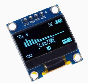
The 0.96-inch I2C OLED Display Module is a compact, high-contrast monochrome screen designed to bring crisp visual output to your electronics projects. Featuring the SSD1306 driver IC and a sharp 128×64 pixel resolution, this display delivers clear text, detailed graphics, and custom icons in a vibrant blue color . The module uses the popular I2C protocol for communication, requiring only two data lines (SDA and SCL) to connect to your microcontroller .
Unlike traditional LCDs that require a backlight, OLED (Organic Light Emitting Diode) technology allows each pixel to emit its own light. This design provides exceptional contrast ratios, true blacks (pixels are completely off), and wide viewing angles exceeding 160° . The result is a professional-looking display that stands out in any lighting condition.
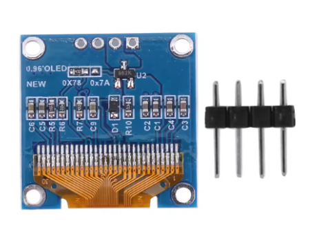
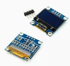
The module includes a transparent protective box for safe storage and protection during transport and handling. Its ultra-low power consumption (approximately 0.08W when the screen is fully lit) makes it an ideal choice for battery-powered applications such as wearable devices, IoT sensors, and portable instruments . With a 4-pin interface and support for both 3.3V and 5V logic, it is compatible with Arduino, Raspberry Pi, ESP32, ESP8266, STM32, and most other microcontroller platforms .
Key Features
-
OLED Technology: Self-emitting pixels provide true blacks, exceptional contrast, and no backlight bleed, resulting in sharp, professional-looking text and graphics .
-
128×64 Pixel Resolution: High-definition display with 128 columns and 64 rows—capable of showing detailed graphics, bitmaps, and up to 8 lines of 21 characters each (depending on font size) .
-
I2C Interface: 2-wire communication protocol (4 pins total) requires only 2 data lines (SDA and SCL), preserving valuable I/O pins for other sensors and peripherals .
-
SSD1306 Driver IC: Industry-standard controller with built-in display buffer, oscillator, and support for common graphics libraries .
-
Wide Voltage Compatibility: Operates on both 3.3V and 5V logic with an operating range of approximately 2.8V to 5.2V—directly compatible with most microcontrollers without level shifters .
-
Ultra-Low Power Consumption: Consumes approximately 0.08W when fully lit, making it excellent for battery-powered and portable projects .
-
Wide Viewing Angle: >160° visibility ensures clear readouts from almost any angle without contrast shift .
-
Pre-soldered 4-Pin Header: Ready to use out of the box—pins are already soldered for breadboard compatibility .
-
Transparent Protective Box: Includes a durable clear storage box to protect the module during transport and extend its service life.
-
Industrial Temperature Range: Operates reliably from -30°C to +70°C, suitable for a variety of environments .
Technical Specifications
Pinout & Connection Guide
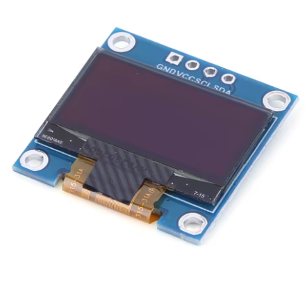
The module uses a straightforward 4-pin interface, clearly labeled on the back of the PCB.
I2C Pin Mapping for Common Development Boards
Wiring Diagram (Arduino Uno)
OLED Module          →    Arduino Uno
─────────────────────────────────────
VCC (VDD)            →    5V (or 3.3V)
GND                  →    GND
SCL (SCK)            →    A5 (SCL)
SDA                  →    A4 (SDA)
Important Note: The silkscreen on your specific module may use slightly different labels (e.g., VDD instead of VCC, or SCK instead of SCL). Always verify the pin markings on the back of your board before wiring .
Usage Guide
Software Setup (Arduino IDE)
To get your OLED display up and running quickly, you will need to install two essential libraries: Adafruit GFX (provides graphics primitives) and Adafruit SSD1306 (provides hardware driver support) .
Step 1: Install the Required Libraries
-
Open Arduino IDE → Sketch → Include Library → Manage Libraries
-
In the Library Manager, search for “Adafruit SSD1306”
-
Click Install (this will also prompt you to install Adafruit GFX as a dependency — click Install All)
Step 2: Verify I2C Address (I2C Scanner)
Before running the main sketch, it is good practice to confirm your display’s I2C address. Most modules default to 0x3C, but some may use 0x3D .
Upload this I2C scanner sketch to find your display’s address:
#include <Wire.h>

void setup() {
  Wire.begin();
  Serial.begin(9600);
  Serial.println("I2C Scanner");
}

void loop() {
  byte error, address;
  int nDevices = 0;

  for(address = 1; address < 127; address++) {
    Wire.beginTransmission(address);
    error = Wire.endTransmission();

    if(error == 0) {
      Serial.print("I2C device found at address 0x");
      if(address < 16) Serial.print("0");
      Serial.println(address, HEX);
      nDevices++;
    }
  }

  if(nDevices == 0) Serial.println("No I2C devices found");
  delay(5000);
}
Step 3: Basic Test Sketch
#include <Wire.h>
#include <Adafruit_GFX.h>
#include <Adafruit_SSD1306.h>
#define SCREEN_WIDTH 128
#define SCREEN_HEIGHT 64
#define OLED_ADDR 0x3C
Adafruit_SSD1306 display(SCREEN_WIDTH, SCREEN_HEIGHT, &Wire, -1);
void setup() {
Serial.begin(9600);
if(!display.begin(SSD1306_SWITCHCAPVCC, OLED_ADDR)) {
Serial.println(F("SSD1306 allocation failed"));
for(;;);
}
display.clearDisplay();
display.setTextSize(2);
display.setTextColor(SSD1306_WHITE);
display.setCursor(20, 25);
display.println("OLED Ready!");
display.display();
}
void loop() {
}
Understanding the Display Buffer Workflow
The Adafruit_SSD1306 library uses a buffer-based drawing system :
-
Drawing functions (e.g., drawPixel, println, fillRect) write to an in-memory buffer
-
The screen does NOT update immediately
-
You must call display.display() to transfer the buffer contents to the actual OLED panel
This approach allows you to build complex screens without visible flickering.
Basic Graphics Functions
display.clearDisplay();
display.drawPixel(10, 10, SSD1306_WHITE);
display.drawLine(0, 0, 127, 63, SSD1306_WHITE);
display.drawRect(10, 10, 50, 30, SSD1306_WHITE);
display.fillRect(70, 10, 40, 30, SSD1306_WHITE);
display.drawCircle(64, 32, 20, SSD1306_WHITE);
display.fillCircle(64, 32, 15, SSD1306_WHITE);
display.setTextSize(1);
display.setTextColor(SSD1306_WHITE);
display.setCursor(0, 55);
display.print("Graphics Demo");
display.display();
Using the U8g2 Library (Alternative)
The U8g2 library is another popular option that offers more fonts and advanced features . Install it via Library Manager, then use this basic initialization:
#include <Arduino.h>
#include <U8g2lib.h>
#include <Wire.h>

U8G2_SSD1306_128X64_NONAME_F_HW_I2C u8g2(U8G2_R0, U8G2_PIN_NONE);

void setup() {
  u8g2.begin();
  u8g2.enableUTF8Print();
}

void loop() {
  u8g2.firstPage();
  do {
    u8g2.setFont(u8g2_font_ncenB08_tr);
    u8g2.drawStr(0, 20, "Hello World!");
  } while ( u8g2.nextPage() );
  delay(1000);
}
Raspberry Pi (Python) Setup
The display also works with Raspberry Pi using Python libraries:
import board
import busio
import adafruit_ssd1306
from PIL import Image, ImageDraw, ImageFont
i2c = busio.I2C(board.SCL, board.SDA)
oled = adafruit_ssd1306.SSD1306_I2C(128, 64, i2c)
oled.fill(0)
oled.show()
oled.text("Hello Pi!", 0, 0, 1)
oled.show()
Power Management for Battery-Powered Projects
OLED displays are excellent for low-power applications because only lit pixels consume power .
Power-Saving Tips:
-
Use display.ssd1306_command(SSD1306_DISPLAYOFF) followed by display.ssd1306_command(SSD1306_DISPLAYON) to put the display in standby when not needed
-
Avoid displaying bright static content for extremely long periods to prevent uneven pixel aging
-
For battery-powered applications, consider updating the display only when values change
Q: What is the difference between this OLED and a standard LCD?
OLED pixels emit their own light, so no backlight is required. This provides true blacks (pixels are completely off), much higher contrast, and wider viewing angles (>160°) . Traditional LCDs use a backlight, which constantly draws power and cannot achieve true black
Q: What is the difference between the 0.96" and 0.91" OLED displays?
The 0.96″ version offers 128×64 pixels (64 rows tall), allowing up to 8 lines of small text or detailed graphics. The 0.91″ version is only 128×32 pixels (32 rows tall), supporting about 2-3 lines of text. The 0.96″ display provides significantly more screen real estate for complex interfaces.
Q: Does this display support grayscale or color?
No. This is a monochrome (single-color) display. Each pixel is either ON (blue) or OFF (black). While the SSD1306 driver itself supports 4-bit grayscale modulation (16 levels per pixel via PWM), most I2C libraries do not implement this feature in a user-friendly way. Standard implementations are binary .
Q: How many characters can the display show?
With the default 8×8 pixel font, the display can show approximately 16 characters × 8 lines = 128 characters total. With larger fonts (e.g., 16×16 pixels), fewer characters fit .
Q: What is the lifespan of the OLED display?
OLEDs have a rated lifespan of approximately 20,000-30,000 hours of continuous operation. Displaying the same static image for extremely long periods (e.g., thousands of hours) can cause uneven pixel wear. For typical hobbyist use, this is not a concern .
Q: Can two displays run on the same I2C bus?
Only if they have different addresses. The SSD1306 I2C address is determined by the SA0 pin: typically 0x3C (SA0=0) or 0x3D (SA0=1) . To use two displays, you would need to modify one module by moving a resistor jumper to change its address, or use an I2C multiplexer (e.g., TCA9548A).
Q: How much current does the display draw?
Power consumption is directly related to how many pixels are lit :
-
All pixels off (black screen): ~2mA
-
Full screen white: ~20-25mA
-
Typical text/dashboard: ~10-15mA
Q: Can I adjust the display brightness?
The SSD1306 supports brightness adjustment through the contrast control register using display.ssd1306_command(0x81) followed by a value (0-255). Note that this adjusts the OLED pixel drive current, which affects overall brightness. Lower values reduce power consumption .
Q: Why does my display stay blank/white after power-up?
This usually indicates one of these issues :
-
Incorrect I2C address – run the I2C scanner to confirm (common: 0x3C or 0x3D)
-
Wrong wiring – verify VCC→5V (or 3.3V), GND→GND, SCL→A5, SDA→A4 (for Arduino Uno)
-
Loose connections – check that jumper wires are securely connected
-
Missing display.display() call – drawing functions write to a buffer; you must call display.display() to push the buffer to the screen
Q: Can I use both 3.3V and 5V logic?
Yes, the module is designed to work with both. The operating voltage range is 2.8V to 5.2V, so you can safely power it from either 3.3V or 5V pins on your microcontroller .
Q: What is the transparent box used for?
The transparent protective box provides safe storage for the module, protecting it from dust, moisture, and physical damage during transport and when not in use.
Q: What libraries are available for the SSD1306?
Popular options include:
-
Adafruit_SSD1306 (paired with Adafruit_GFX) – Most popular, well-documented, great for beginners
-
U8g2 – More fonts, advanced features, but slightly steeper learning curve
-
SSD1306Ascii – Lightweight and fast for text-only applications
Q: Why is my text appearing as "garbage" characters or reversed?
You may have the color mode inverted. Ensure you are using SSD1306_WHITE for normal display with a black background. Use SSD1306_BLACK to “erase” pixels .
Q: Can I display images on this OLED?
Yes. Use tools like LCD Image Converter or Image2CPP to convert bitmap images (128×64 monochrome) into C arrays, then use display.drawBitmap(x, y, array, width, height, color) to display them .
Q: Does this library work with ESP32, ESP8266, and STM32?
Yes, the Adafruit_SSD1306 library supports these platforms. For ESP32/ESP8266, the I2C pins may vary by board. For STM32, you may need to initialize the I2C bus as part of your setup . Connection instructions are also available for GD32 and other ARM-based MCUs.
Q: Can I use SPI instead of I2C with this module?
No. This specific 4-pin module is wired for I2C only. The SSD1306 chip supports SPI (4-wire and 3-wire), but those pins are not broken out on this board. For SPI connections, you would need the 7-pin version of the SSD1306 module .