Product Overview
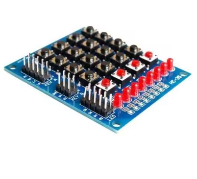
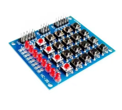
The Matrix Keyboard with LED Display is an all-in-one interactive control module that combines a 4×4 matrix keypad with 8 integrated LEDs, creating a versatile platform for robotics projects, marquee displays, and user interface development . This “independent keyboard” design functions as a complete human-machine interface (HMI) solution, allowing you to both input commands via tactile buttons and receive visual feedback from the built-in LED indicators.
At its core, the module features a 4×5 matrix array (20 physical buttons) structured as a 16-switch matrix with 4 additional independent switches for specialized control functions . The 8 integrated LEDs can be programmed to create flowing light effects (marquee), serve as status indicators, or provide visual confirmation of button presses—perfect for smart car interfaces, robotic control panels, and interactive science projects .
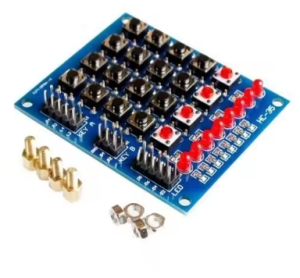
The module is designed with educational and prototyping environments in mind, making it an excellent choice for Arduino programming education, robotics clubs, and electronics training . Its compact dimensions (61mm × 51mm) and included mounting hardware (4 standoffs and screws) allow for easy integration into custom enclosures or direct attachment to robot chassis .
Whether you’re building an interactive marquee sign for a school science fair, a control panel for an autonomous robot, or an educational tool for teaching microcontroller programming, this matrix keyboard with LED display provides a complete, ready-to-use solution that combines input and output capabilities in one convenient module.
Key Features
-
20 Physical Buttons: 16-switch matrix array + 4 independent switches for versatile input control
-
8 Integrated LEDs: Built-in indicators for status feedback, marquee effects, and visual user interaction
-
Independent Keyboard Design: Functions as a standalone input device compatible with Arduino, Raspberry Pi, and other microcontrollers
-
Compact Form Factor: 61mm × 51mm × 12mm dimensions designed for easy integration into robot chassis and project enclosures
-
3.2V – 5V Operating Voltage: Compatible with both 3.3V and 5V logic systems
-
Standard 2.54mm Socket Compatibility: Works with standard breadboards and jumper wires
-
Mounting Hardware Included: 4 standoffs and screws for secure installation
-
Wide Operating Temperature: Designed for reliable operation in various environments
-
Marquee & Animation Ready: Programmable LEDs support scrolling light effects and visual feedback sequences
-
Educational Focus: Ideal for science projects, robot car development, and microcontroller programming education
Technical Specifications
Pinout & Connection Guide
Keypad Matrix Interface
The module uses an 8-pin interface for the 4×5 matrix keypad (4 rows + 4 columns). To use the keypad with Arduino, you’ll need to install the Keypad library and define the appropriate pin mapping.
Typical Wiring Configuration (Arduino):
LED Interface
The 8 LEDs are individually controllable and can be connected to separate digital I/O pins or configured in a matrix to save pins. Each LED requires a current-limiting resistor (typically 220Ω for 5V operation).
Independent Switches
The 4 additional independent switches provide dedicated input lines for specialized control functions, such as mode selection, reset, start/stop, or emergency stop.
Usage Guide
Basic Keypad Scanning (Arduino)
Step 1: Install the Keypad Library
-
Open Arduino IDE → Sketch → Include Library → Manage Libraries
-
Search for “Keypad” by Mark Stanley, Alexander Brevig
-
Click Install
Step 2: Basic Keypad Test Sketch
#include <Keypad.h>
const byte ROWS = 4;
const byte COLS = 4;
char keys[ROWS][COLS] = {
{'1','2','3','A'},
{'4','5','6','B'},
{'7','8','9','C'},
{'*','0','#','D'}
};
byte rowPins[ROWS] = {9, 8, 7, 6};
byte colPins[COLS] = {5, 4, 3, 2};
Keypad keypad = Keypad(makeKeymap(keys), rowPins, colPins, ROWS, COLS);
void setup() {
Serial.begin(9600);
Serial.println("Matrix Keyboard Ready");
}
void loop() {
char key = keypad.getKey();
if (key) {
Serial.print("Key Pressed: ");
Serial.println(key);
switch(key) {
case '1':
break;
case 'A':
break;
}
}
}
Marquee LED Animation (Arduino)
int ledPins[] = {10, 11, 12, 13, A0, A1, A2, A3};
const int ledCount = 8;
void setup() {
for (int i = 0; i < ledCount; i++) {
pinMode(ledPins[i], OUTPUT);
}
}
void marqueeEffect() {
for (int i = 0; i < ledCount; i++) {
digitalWrite(ledPins[i], HIGH);
delay(50);
digitalWrite(ledPins[i], LOW);
}
for (int i = ledCount - 1; i >= 0; i--) {
digitalWrite(ledPins[i], HIGH);
delay(50);
digitalWrite(ledPins[i], LOW);
}
}
void loop() {
marqueeEffect();
}
Independent Switches Usage
The 4 independent switches can be read using standard digitalRead() commands:
const int switchPins[] = {A4, A5, 10, 11};
void setup() {
for (int i = 0; i < 4; i++) {
pinMode(switchPins[i], INPUT_PULLUP);
}
Serial.begin(9600);
}
void loop() {
for (int i = 0; i < 4; i++) {
if (digitalRead(switchPins[i]) == LOW) {
Serial.print("Independent Switch ");
Serial.print(i + 1);
Serial.println(" Pressed");
delay(200);
}
}
}
Q: What is the difference between a matrix keyboard and a standard keypad?
A matrix keyboard arranges buttons in rows and columns, allowing 16 buttons to be read using only 8 I/O pins (4 rows + 4 columns). This design is more efficient for microcontroller projects compared to connecting each button to its own pin . This module adds 8 LEDs for visual output, creating a complete HMI solution.
Q: How many I/O pins does this module require?
The 16-button matrix portion requires 8 pins (4 rows + 4 columns). The 4 independent switches require 4 additional pins, and the 8 LEDs require 8 more pins—totaling up to 20 I/O pins. However, you can use I/O expanders (e.g., PCF8574) or charlieplexing techniques to reduce pin count.
Q: Can I use this module with Raspberry Pi or ESP32?
Yes. The module operates at 3.2V–5V, making it compatible with 3.3V systems (Raspberry Pi, ESP32) and 5V systems (Arduino). For Raspberry Pi, use Python libraries like pad4pi or keypad .
Q: What is a "marquee" effect and how do I create one?
A marquee effect refers to a sequential light pattern where LEDs light up one after another, creating a flowing or chasing effect. You can program this effect by sequentially turning LEDs on and off with small delays, as shown in the usage guide .
Q: Does this module include pull-up resistors for the switches?
Most matrix keypads do not include onboard pull-up resistors. You should enable internal pull-ups in your code (pinMode(pin, INPUT_PULLUP)) or add external 10kΩ pull-up resistors to each row/column line for reliable button detection.
Q: How do I debounce the button inputs to prevent false triggers?
The Keypad library includes built-in debouncing logic that handles switch bounce automatically . For the independent switches, implement software debouncing with a delay (typically 50-100ms) after detecting a button press.
Q: Can the 8 LEDs be individually controlled for custom animations?
Yes, each of the 8 LEDs is independently controllable. You can create custom lighting patterns, respond to button presses with visual feedback, or create complex marquee animations for interactive displays .
Q: Is this module suitable for educational use with students?
Absolutely. This module is specifically designed for educational settings and is used in science kits, high school robotics projects, and microcontroller programming courses . It provides tangible input/output interaction that helps students understand programming concepts.
Q: What is the "independent keyboard" feature?
The “independent keyboard” refers to the ability to use this module as a standalone input device, similar to a computer numeric keypad, without requiring complex additional circuitry . The 4 independent switches provide dedicated control functions separate from the matrix.
Q: How do I mount this module to my robot or enclosure?
The module includes 4 standoffs and screws . Mounting holes are spaced at 55mm × 45mm . You can attach the module directly to your robot chassis or project enclosure using the included hardware.