Product Overview
The 600W DC-DC Boost Converter Module is a professional-grade, high-power step-up voltage regulator engineered for demanding applications requiring efficient voltage elevation. This non-isolated boost converter accepts a wide DC input range of 12V to 60V and delivers an adjustable output of 12V to 90V with up to 600W of output power.
What sets this module apart is its Constant Voltage (CV) and Constant Current (CC) control capability, making it ideal for lithium battery charging, high-power LED driving, solar system boosting, and industrial equipment power supply. Independent multi-turn potentiometers allow precise adjustment of both output voltage and current limit, giving you complete control over your power delivery .
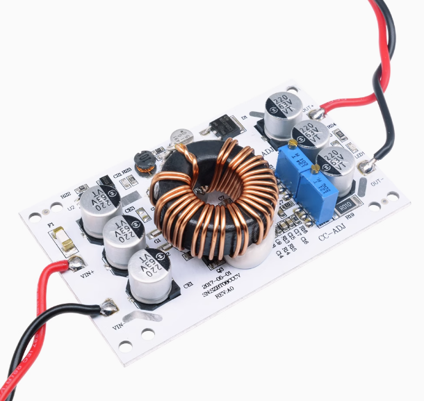
The module is built on an aluminum substrate PCB for excellent thermal conductivity and features an integrated heatsink (5mm thick base plate, 21mm fins) that doubles as a mounting plate. The 27mm iron silicon aluminum magnetic ring inductor with 1mm dual-wire windings ensures high efficiency and stable performance under load .
Effective Power Note: Due to the 10A input current limit, the effective output power equals input voltage × 10A. For example, 12V input × 10A = 120W effective output; 60V input × 10A = 600W output. This is not a limitation of the module but a result of the 150kHz switching regulator design—the input current capacity determines achievable output power at lower input voltages .
Key Features
-
600W High Power Output: Delivers up to 600W of output power (effective power = input voltage × 10A). Two modules can be connected in parallel to increase current capacity .
-
Adjustable CV/CC Control: Independent multi-turn potentiometers allow precise setting of output voltage (12-90V) and constant current limit, essential for battery charging and LED driving .
-
Wide Input/Output Range: Accepts DC input from 12V to 60V, with output adjustable from 12V to 90V. Input voltage must be lower than output voltage .
-
High Conversion Efficiency: Achieves up to 95% efficiency at 150kHz switching frequency, minimizing power loss and heat generation .
-
Output Anti-Reverse Protection: Built-in protection prevents current backflow when used for battery charging – no external diode required .
-
Overcurrent & Short Circuit Protection: Includes input overcurrent protection (reduces output when input exceeds ~17A) and 20A fuse for short circuit protection .
-
Compact Integrated Heatsink: 5mm thick aluminum base plate with 21mm fins provides effective passive cooling; active cooling recommended for loads >10A .
-
Wide Operating Temperature: Rated for -40°C to +85°C, suitable for demanding environments .
Technical Specifications
Pinout & Connection Guide
The module uses clearly labeled screw terminals for input and output connections .
Input Terminals (Power Source)
Output Terminals (Load Connection)
Adjustment Controls
Additional Features
⚠️ Critical Safety Notes:
-
This module has NO input reverse polarity protection – connecting input backward will damage the module
-
The module cannot regulate output voltage below input voltage (boost only)
-
Power on the module first, then connect the load – especially important for high-power loads
Usage Guide
Important First-Time Setup
⚠️ Use a Multimeter: The factory default output is often set to a random voltage (typically 19V) . Always measure the output with a multimeter before connecting your load and adjust the CV potentiometer to the exact voltage required.
Wiring Instructions
-
Select Input Range: Use the onboard jumper to select appropriate input range – 8-16V for 12V battery applications, or 12-60V for wide-range input .
-
Set Initial Outputs: Before powering on, turn both potentiometers counter-clockwise about 20 turns to set minimum .
-
Connect Input: Connect your DC power source to the IN+ and IN- terminals. Ensure correct polarity (no reverse protection). Add a series diode for protection if needed .
-
Set Output Voltage (CV Mode): Place a multimeter on output terminals. Apply input power. Slowly turn CV potentiometer counter-clockwise until reaching desired voltage .
-
Set Current Limit (CC Mode) :
-
For LED loads: Set CC potentiometer to minimum, connect LED, then slowly increase CC pot while monitoring ammeter
-
For battery charging: Use a discharged battery when setting the current limit – a charged battery will draw less current
-
Important: Do not short the output to set current – the boost converter circuit cannot regulate current in a short-circuit condition
-
Connect Permanent Load: Turn off input power, connect your permanent load, and re-apply power.
Thermal Management & Power Derating
The maximum output power depends on the input/output voltage differential and cooling:
Important: This module struggles at low input voltages (near 12V) under high load without forced air cooling . Always use active cooling for loads >10A.
Cooling Fan Setup
The DC barrel jack can be repurposed to power a 12V or 24V cooling fan :
-
12V fan: Spins at nominal speed with 12V input; may run faster at higher voltages
-
24V fan: Provides good cooling across 12-35V input range (spins slower at 12V)
-
Mounting: No dedicated fan mounting points – you’ll need to design a bracket or lean a fan against the heatsink
Typical Applications
Q: How much real power can this module actually deliver?
The module’s effective power equals input voltage × 10A. For example, 12V input × 10A = 120W effective output; 60V input × 10A = 600W output . To achieve full 600W, you need at least 48V input. The module draws up to 15A input current peak, but sustained operation above 10A requires active cooling .
Q: Why does my 12V system struggle to deliver high power?
This module does not perform well at 12V input under high load without a cooling fan . At 12V input, it’s limited to approximately 10-12A input current (120-144W output power). For 48V-60V output applications, start with a 24V-36V input for better performance.
Q: Can this module regulate current down to 0A?
No. This module cannot regulate current down to zero – it has a minimum current that drifts . This is important for applications requiring very low currents, such as trickle charging.
Q: How do I set up current limiting for battery charging?
Set the output voltage to the battery’s float voltage, then adjust the current limit while connected to a discharged battery . The module has output anti-reverse protection, so no external diode is needed for charging applications .
Q: Do I need a cooling fan for this module?
For loads under 200W, passive cooling may suffice. For loads above 200W or with input below 24V, a cooling fan is highly recommended . The DC barrel jack can be used to power a 12V fan .
Q: Why does the module have two power inputs?
The screw terminal is for main power input. The DC barrel jack serves as an alternative input but is best used as a convenient 12V fan power connector . This allows the fan to run directly from the input source.
Q: What happens if I exceed the input current limit?
The module has overcurrent protection that automatically reduces output voltage when input current exceeds approximately 17A . The 20A fuse provides additional short circuit protection.
Q: Can I use this module to power LED lights directly?
Yes, using constant current (CC) mode. However, note that some LED types may not work well with pulsed DC output . Test with your specific LEDs before permanent installation. For LED applications, set CC mode to the LED’s rated current .
Q: Can I connect two modules in parallel for more power?
Yes, with caution. Two or more modules can be connected in parallel to increase output current. For example, if you need 15A output, use two modules in parallel with each adjusted to 8A . Ensure the input power supply can handle the combined current draw.
Q: What safety features does this module include?
The module includes:
-
Output anti-reverse protection (for battery charging)
-
Overcurrent protection (reduces output at ~17A input)
-
Short circuit protection (20A fuse)
-
No input reverse polarity protection – add external diode