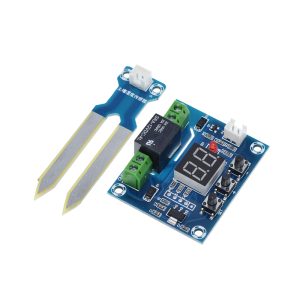
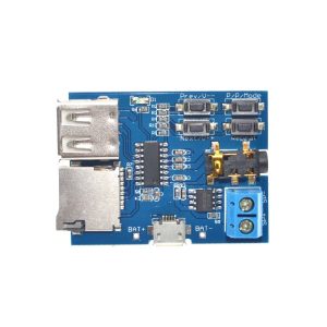
Product Overview
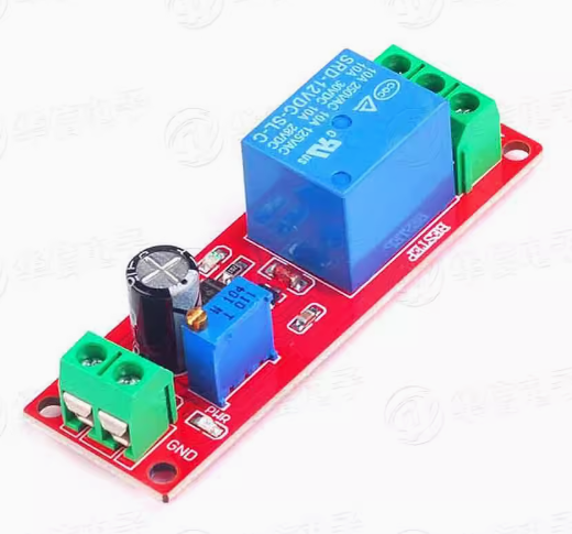
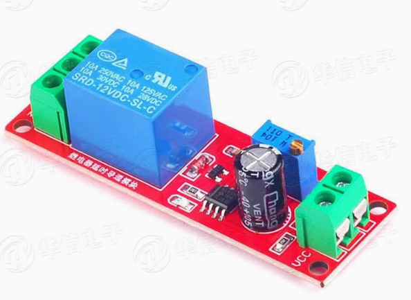
The NE555 Delay Monostable Switch Module is a compact, high-performance timing control board designed to provide precise and adjustable time delays for 12V vehicle electrical systems and industrial automation applications. Based on the legendary NE555 timer IC from Texas Instruments – one of the most popular and reliable integrated circuits in history – this module generates accurate timing pulses for equipment needing a delayed startup or shutdown sequence.
The module operates in monostable mode, meaning it produces a single, stable output pulse each time it receives a trigger signal. When a low-level trigger signal is applied (such as pressing a button or receiving a signal from a sensor), the output relay instantly activates and remains active for a preset duration before automatically deactivating. This makes it ideal for applications like protecting vehicle electronics during ignition, preventing current surge damage, and controlling lights, fans, pumps, or other electrical loads.
The onboard potentiometer allows stepless adjustment of the delay time, typically ranging from 0 to 10 seconds, with the ability to extend the delay range by replacing the timing capacitor. An ultra-bright LED provides visual confirmation of the relay’s active state, and the built-in relay supports loads up to 250V AC at 10A or 30V DC at 10A, making it suitable for controlling both high-voltage household appliances and low-voltage DC equipment.
Key Features
-
Monostable Timing Mode: The module triggers a single timing pulse when a low-level signal is received – perfect for equipment requiring a delayed start after ignition or button press.
-
Adjustable Delay Time: Onboard potentiometer allows stepless adjustment from 0 to 10 seconds; the range can be extended by replacing the timing capacitor.
-
12V DC Operation: Designed specifically for 12V vehicle systems, including cars, trucks, boats, and other automotive equipment.
-
High-Power Relay Output: Built-in relay rated at 250V AC / 10A and 30V DC / 10A, capable of controlling lights, fans, pumps, motors, and other electrical loads.
-
Easy Triggering: The module activates with a low-level signal (0V), making it simple to interface with switches, sensors, or microcontroller outputs.
-
Visual Status Indicators: Power indicator LED confirms module is powered, while a separate timer LED indicates when the relay is active and the timing cycle is running.
-
Compact Design: Small footprint allows easy mounting inside vehicle fuse boxes, equipment enclosures, or control panels.
-
Low Standby Power Consumption: The module draws minimal current when idle, preserving vehicle battery life.
Technical Specifications
Pinout & Connection Guide
The module features clearly labeled screw terminals for simple wiring.
Input Terminals (Power & Trigger)
Output Terminals (Relay Load)
Typical Wiring for Vehicle Equipment:
-
Connect DC+ to a switched 12V source (e.g., ACC or ignition)
-
Connect DC- to vehicle ground (chassis)
-
Connect TRIG to a push-button switch that connects to ground when pressed
-
Connect your load (e.g., radio, fan, pump) to COM and NO terminals
Usage Guide
Monostable Operation (One-Shot Mode)
In monostable mode, the module behaves as follows:
-
Idle State (Steady State): The relay is OFF (NO open, NC closed). The timer LED is OFF. The module waits for a trigger signal.
-
Trigger Event: When the TRIG terminal receives a low-level signal (0V), the timing cycle begins immediately. The relay activates (NO closes, NC opens), and the timer LED illuminates.
-
Timing Period: The output remains active for the preset duration (0–10 seconds). The timing interval is determined by the potentiometer and timing capacitor.
-
Cycle Completion: Once the preset time elapses, the relay automatically deactivates, the timer LED turns off, and the module returns to its idle state, ready for the next trigger signal.
Important: During the timing cycle, additional trigger pulses are ignored. The circuit is “non-retriggerable,” ensuring the timing period completes without interruption.
Adjusting the Delay Time
The onboard potentiometer allows stepless adjustment of the delay time:
Extending the Delay Range: The delay formula is T = 1.1 × R × C. To achieve longer delays, replace the 100µF timing capacitor (C1) with a larger value.
Protection for Vehicle Installations
When installing in vehicles, the module provides protection during ignition cranking:
-
Connect the module’s power to an “ignition-switched” +12V source (not constant battery power)
-
The trigger input (TRIG) can be connected to a momentary push-button or the ignition switch itself
-
When you turn the key to START, the cranking process can be delayed to prevent voltage sags from affecting sensitive equipment
Wiring Example for Delay-On (After Ignition)
-
Power: Connect DC+ to an ACC (accessory) or IGN (ignition) +12V source.
-
Trigger: Connect the TRIG terminal directly to the same +12V source (or to a switch).
-
Load: Connect your protected equipment (radio, amplifier, display) to the relay’s COM and NO terminals.
When you turn the ignition ON, the TRIG signal immediately starts the timing cycle. The equipment will power ON only after the preset delay elapses – perfect for letting the engine stabilize before powering sensitive devices.
Using with Arduino / Microcontrollers
The module’s TRIG input accepts standard TTL low-level signals (0V), making it easy to interface with Arduino, ESP32, or other microcontroller outputs. Simply connect a digital output pin to the TRIG terminal and set it LOW to trigger the delay sequence.
Q: What does "monostable mode" mean and how does it work?
In monostable mode, the module acts as a “one-shot” timer. When triggered, the output activates for a fixed duration (set by the potentiometer and capacitor), then automatically turns off and waits for the next trigger. It has only one stable state (OFF) and one temporary state (ON)
Q: What types of loads can I control with this module?
The built-in relay supports both AC and DC loads up to 10 Amps. This includes:
-
AC loads: Lamps, fans, small pumps, heaters (up to 250V/10A)
-
DC loads: 12V LED lights, DC motors, solenoids, water pumps (up to 30V/10A)
Q: Can I use this module to delay the startup of my car radio or amplifier?
Yes, this is a common application. Connect the module’s power to an ignition-switched 12V source, and connect the radio’s power to the relay output. Set the delay time to 5-10 seconds, and your radio will power ON only after the engine has started and voltage has stabilized
Q: How can I make the delay time longer than 10 seconds?
The delay formula is T = 1.1 × R × C, where R is the resistance (potentiometer) and C is the capacitance (timing capacitor). To increase the delay, either:
-
Increase the resistance by turning the potentiometer clockwise
-
Replace the timing capacitor (typically 100µF) with a larger value (e.g., 220µF or 470µF)
Q: Can the module be triggered multiple times while it is already running?
No. The circuit is “non-retriggerable.” During the timing cycle, any additional trigger pulses are ignored, ensuring the timing period completes without interruption. This is ideal for applications requiring a guaranteed minimum ON time.
Q: Does this module work with 24V vehicles (trucks, buses)?
The standard version is designed for 12V operation. For 24V systems, either:
Q: What is the quiescent (standby) current draw when idle?
The module draws minimal current when idle (relay OFF), as the NE555 chip and relay driver circuit are in a low-power state. This makes it suitable for direct connection to vehicle batteries without significant drain.
Q: Can I use this module with a push-button switch?
Yes. Connect one side of the push-button to the TRIG terminal and the other side to GND. Pressing the button provides a low-level (0V) trigger signal that starts the timing cycle
Q: Is the module protected against reverse polarity?
Most NE555 modules do NOT include reverse polarity protection. Always double-check your connections before applying power to prevent damage.
Q: What is the minimum trigger pulse width required?
The NE555 trigger input responds to low-level signals lasting longer than the propagation delay (typically microseconds). A momentary switch press or microcontroller pulse of 10ms is more than sufficient.