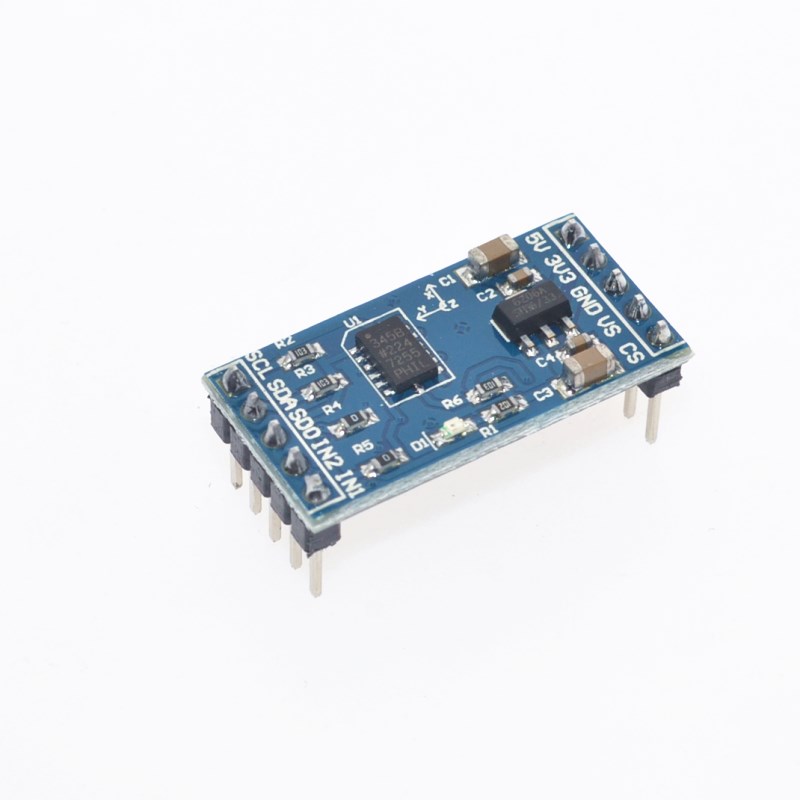
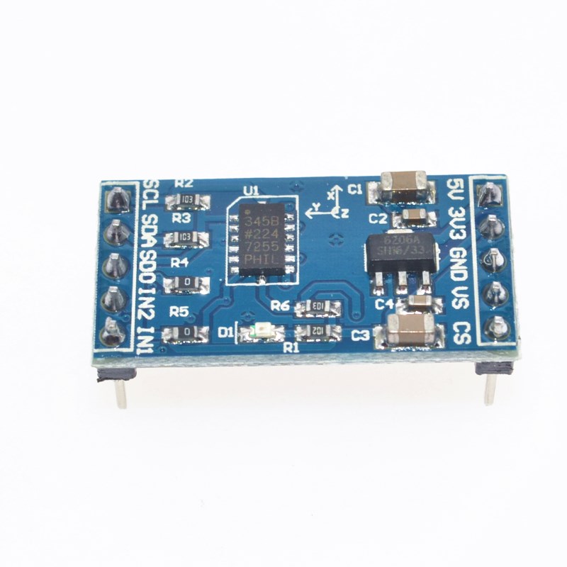
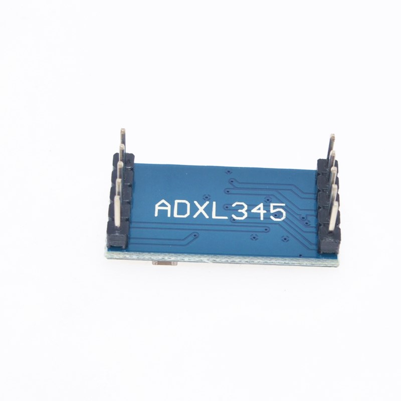
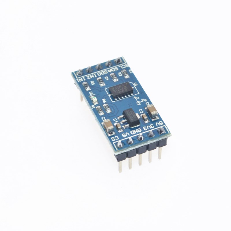
Product Overview
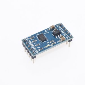
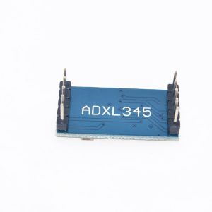
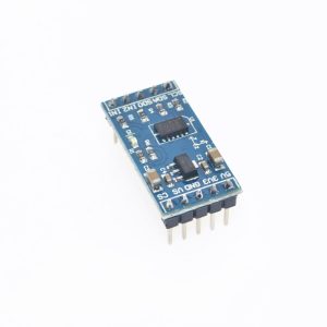
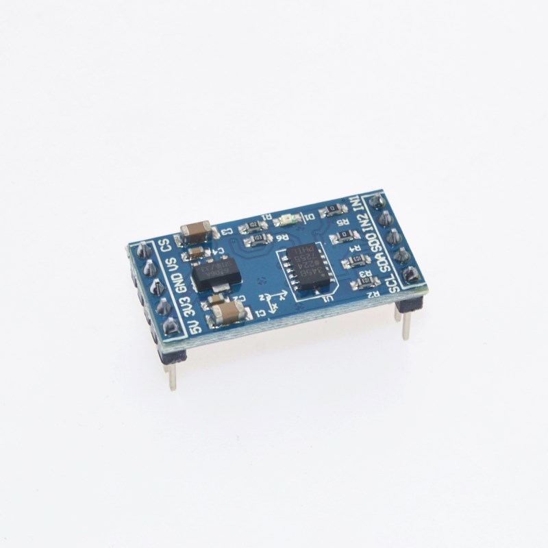
The ADXL345 Digital Angle Acceleration Sensor Module is a high-performance, ultra-low power, 3-axis accelerometer designed to measure both static gravity (for tilt/inclination) and dynamic acceleration (from motion or shock). Built around the industry-standard Analog Devices ADXL345 chip, this module is widely used in robotics, IoT devices, smartphones, gaming controllers, and industrial monitoring systems.
Unlike analog accelerometers that require complex ADC calculations, the ADXL345 provides digital output via I2C or SPI interfaces, delivering 16-bit digital values directly to your microcontroller . With selectable measurement ranges of ±2g, ±4g, ±8g, and ±16g and up to 13-bit resolution, it can detect inclination changes of less than 1.0° .
The module features an onboard 3.3V voltage regulator and logic-level shifting, making it compatible with both 3.3V and 5V microcontrollers like Arduino, ESP32, ESP8266, STM32, and Raspberry Pi . Its advanced motion detection capabilities—including tap/double-tap detection, free-fall detection, and activity/inactivity monitoring—enable sophisticated gesture and context-aware applications without burdening the host processor.
Key Features
-
3-Axis Digital Accelerometer: Simultaneously measures acceleration on X, Y, and Z axes for comprehensive motion and tilt sensing .
-
Selectable Measurement Ranges: User-selectable ranges of ±2g, ±4g, ±8g, and ±16g, allowing optimization for either sensitive tilt detection or high-impact shock measurement .
-
High Resolution: Up to 13-bit resolution (4 mg/LSB scale factor in all g-ranges), enabling precise detection of inclination changes less than 1.0° .
-
Ultra-Low Power Consumption: Consumes as little as 23 µA in measurement mode and 0.1 µA in standby mode (at 2.5V), making it ideal for battery-powered IoT and wearable devices .
-
Dual Digital Interfaces: Supports both I2C and SPI (3-wire or 4-wire) communication protocols for maximum flexibility with different microcontrollers .
-
Built-in Motion Detection Features:
-
Single/Double Tap Detection for gesture recognition
-
Free-Fall Detection for drop protection applications
-
Activity/Inactivity Monitoring for intelligent power management
-
32-Level FIFO Buffer: Integrated memory buffer stores up to 32 samples, reducing host processor load and enabling burst data collection while the microcontroller sleeps .
-
Programmable Interrupt Pins: Two interrupt pins (INT1, INT2) can be mapped to specific events (data ready, tap, free-fall, etc.) for efficient wake-up and event-driven systems .
-
Wide Operating Voltage: Core sensor operates from 2.0V to 3.6V; breakout boards typically include 3.3V regulators and level shifters for 5V compatibility .
-
Industrial Temperature Range: Rated for -40°C to +85°C (standard) with -55°C to +105°C available on EP version, suitable for demanding environments .
Technical Specifications
Pinout & Interface Guide
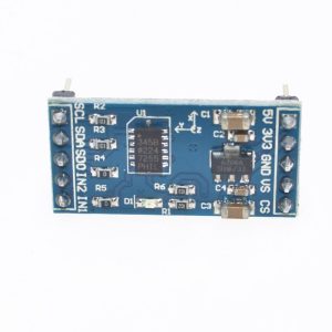
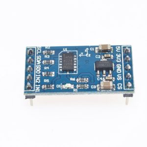
The breakout module typically provides an 8-pin 2.54mm header for easy breadboard connection.
I2C Addressing:
Usage Guide
Hardware Wiring
I2C Mode (Recommended – Uses only 2 pins) :
SPI Mode (Faster data rates) :
Software Setup (Arduino IDE)
Step 1: Install the Library
The easiest way to use the ADXL345 is with the Adafruit ADXL345 library.
-
Open Arduino IDE → Sketch → Include Library → Manage Libraries
-
Search for “Adafruit ADXL345”
-
Click Install (this will also install the Adafruit Sensor and BusIO libraries)
Step 2: Basic Read Example (I2C Mode)
#include <Wire.h>
#include <Adafruit_Sensor.h>
#include <Adafruit_ADXL345_U.h>
Adafruit_ADXL345_Unified accel = Adafruit_ADXL345_Unified(12345);
void setup() {
Serial.begin(9600);
if (!accel.begin()) {
Serial.println("Could not find ADXL345");
while (1);
}
accel.setRange(ADXL345_RANGE_16_G);
Serial.println("ADXL345 Ready");
}
void loop() {
sensors_event_t event;
accel.getEvent(&event);
Serial.print("X: "); Serial.print(event.acceleration.x);
Serial.print(" | Y: "); Serial.print(event.acceleration.y);
Serial.print(" | Z: "); Serial.println(event.acceleration.z);
delay(100);
}
Step 3: Calculate Tilt Angle (Pitch & Roll)
float pitch = atan2(event.acceleration.y, event.acceleration.z) * 180 / PI;
float roll = atan2(-event.acceleration.x, sqrt(event.acceleration.y * event.acceleration.y + event.acceleration.z * event.acceleration.z)) * 180 / PI;

Serial.print("Pitch: "); Serial.print(pitch);
Serial.print(" | Roll: "); Serial.println(roll);
Power Considerations
The ADXL345 core operates at 2.0V–3.6V. Most breakout boards include an LDO voltage regulator and level shifters, allowing direct connection to 5V microcontrollers . However, the sensor’s I/O pins are not 5V tolerant—the level shifters on quality breakout boards handle this conversion .
For battery-powered applications, use the low-power modes:
-
Standby Mode: 0.1 µA – Place sensor in standby when not in use
-
Lower Output Data Rate: Reduce ODR to minimize active current
-
Use FIFO Buffer: Collect multiple samples before waking the host MCU
Understanding the Data
The accelerometer outputs represent acceleration in meters per second squared (m/s²). At rest, the Z-axis will read approximately 9.8 m/s² (gravity), while X and Y axes will read near 0 m/s² .
-
Positive values: Acceleration in the positive axis direction
-
Negative values: Acceleration in the negative axis direction
-
Inclination/tilt: Can be calculated using trigonometric functions from the three axes
Q: What is the difference between ADXL345 and ADXL335?
The ADXL345 provides digital output (I2C/SPI), has selectable ranges up to ±16g, and includes advanced features like tap detection and FIFO buffering. The ADXL335 provides analog output, has a fixed ±3g range, and lacks built-in detection features. For modern microcontrollers, the digital interface of the ADXL345 is significantly easier to use .
Q: Can the ADXL345 detect tilt/angle accurately?
Yes. With its 13-bit resolution (4 mg/LSB) and selectable ±2g range, it can detect inclination changes of less than 1.0 degree . For best results, use the ±2g range and apply a moving average filter to smooth the readings.
Q: What is the FIFO buffer used for?
The 32-level FIFO buffer stores acceleration samples without requiring the host microcontroller to read each sample individually. This allows the MCU to sleep between readings, significantly reducing overall system power consumption—critical for battery-powered IoT devices .
Q: Is the ADXL345 compatible with 5V microcontrollers like Arduino Uno?
Yes, with a proper breakout board. The ADXL345 core operates at 3.3V, but quality breakout modules include onboard voltage regulators and level shifters that make the I2C/SPI pins 5V tolerant. Always verify your specific board includes level shifting before connecting to 5V .
Q: What is the maximum sampling rate?
The maximum output data rate (ODR) is 3200 Hz . At this rate, power consumption increases significantly (approx. 140 µA), but it is suitable for vibration analysis and high-frequency motion capture applications.
Q: How do I select the appropriate measurement range?
Use ±2g for tilt sensing and inclination measurement (highest sensitivity). Use ±4g or ±8g for general motion detection (e.g., step counting, gesture recognition). Use ±16g for detecting shocks, impacts, or high-acceleration events .
Q: How does free-fall detection work?
Free-fall detection is triggered when all three axes measure near 0g simultaneously (indicating the device is in free fall). This is typically used to protect hard drives by parking the read/write heads before impact .
Q: Can I use the ADXL345 with a Raspberry Pi?
Yes. Connect via I2C using the SDA and SCL pins, or via SPI. Enable I2C using raspi-config, install the python3-smbus package, and use Python libraries like Adafruit_Blinka or adafruit-circuitpython-adxl34x .
Q: What causes "Invalid ADXL345 ID" errors in Klipper/3D printers?
This error typically indicates a loose connection, damaged cable, or incompatible firmware versions. Check the physical connection between the accelerometer and controller board, then verify that the firmware versions (mainboard and screen) are compatible .
Q: Where can I find the official documentation?
The complete ADXL345 datasheet and application notes are available from Analog Devices (www.analog.com) . Additional library examples and wiring guides are available on the Adafruit Learning System and the Arduino Library Manager.