Product Overview
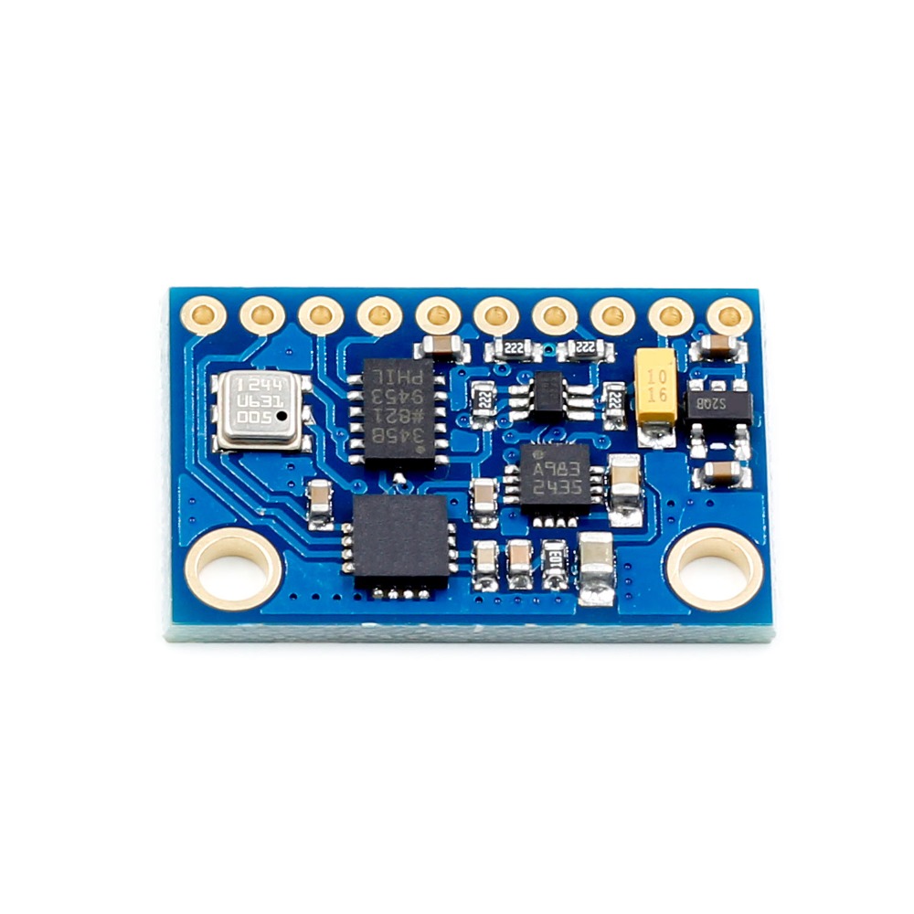
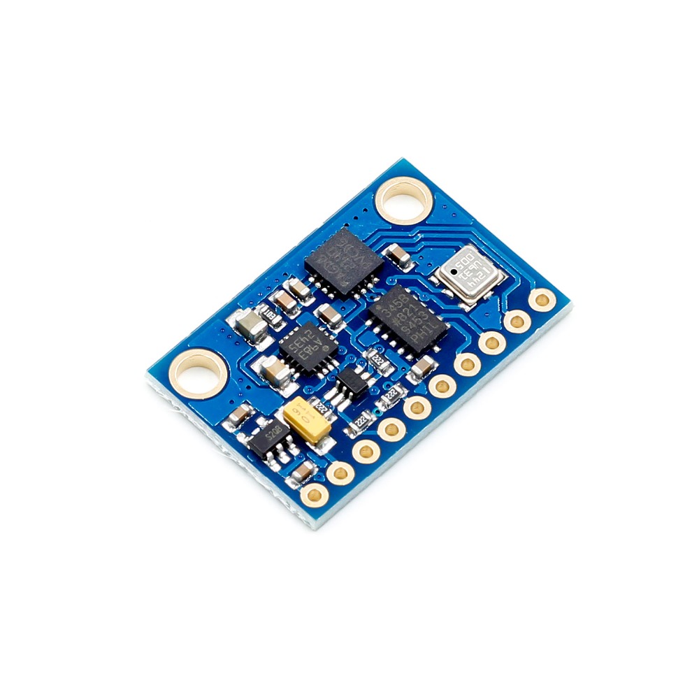
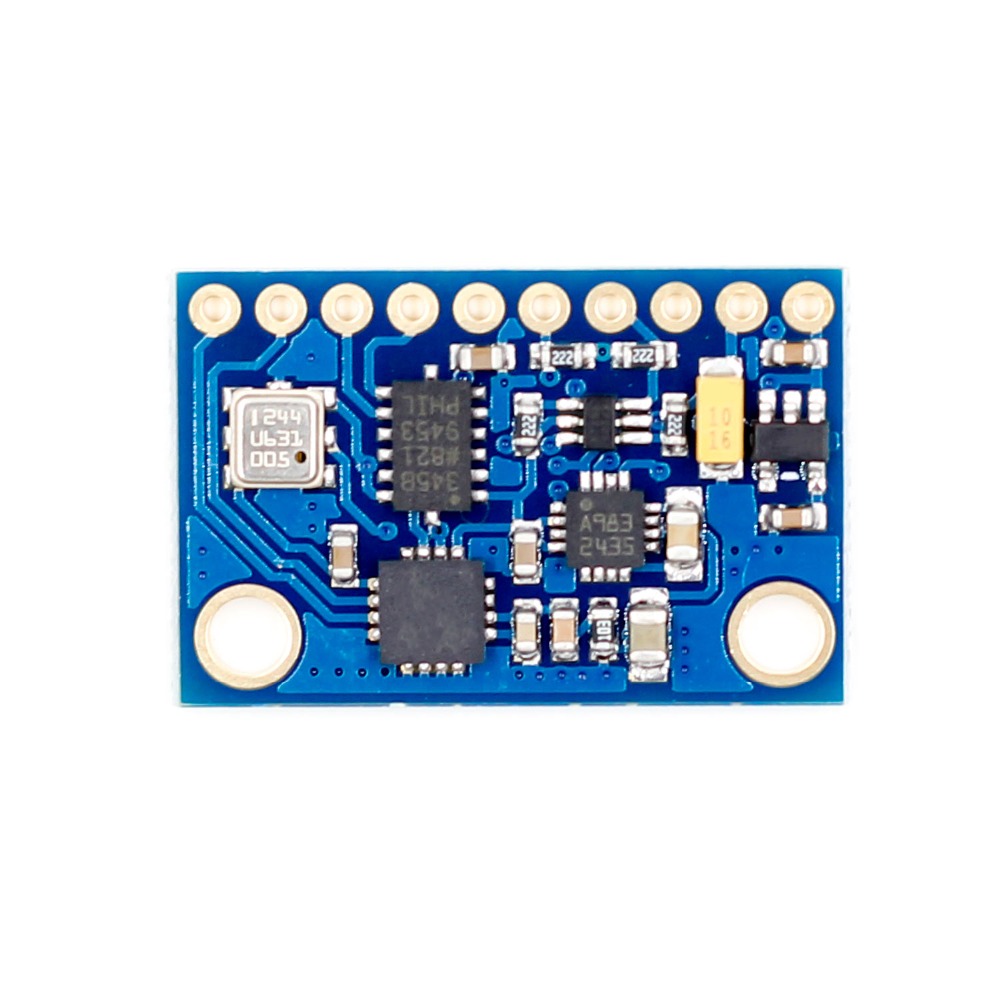
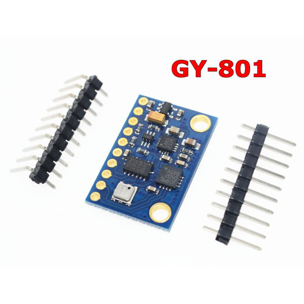
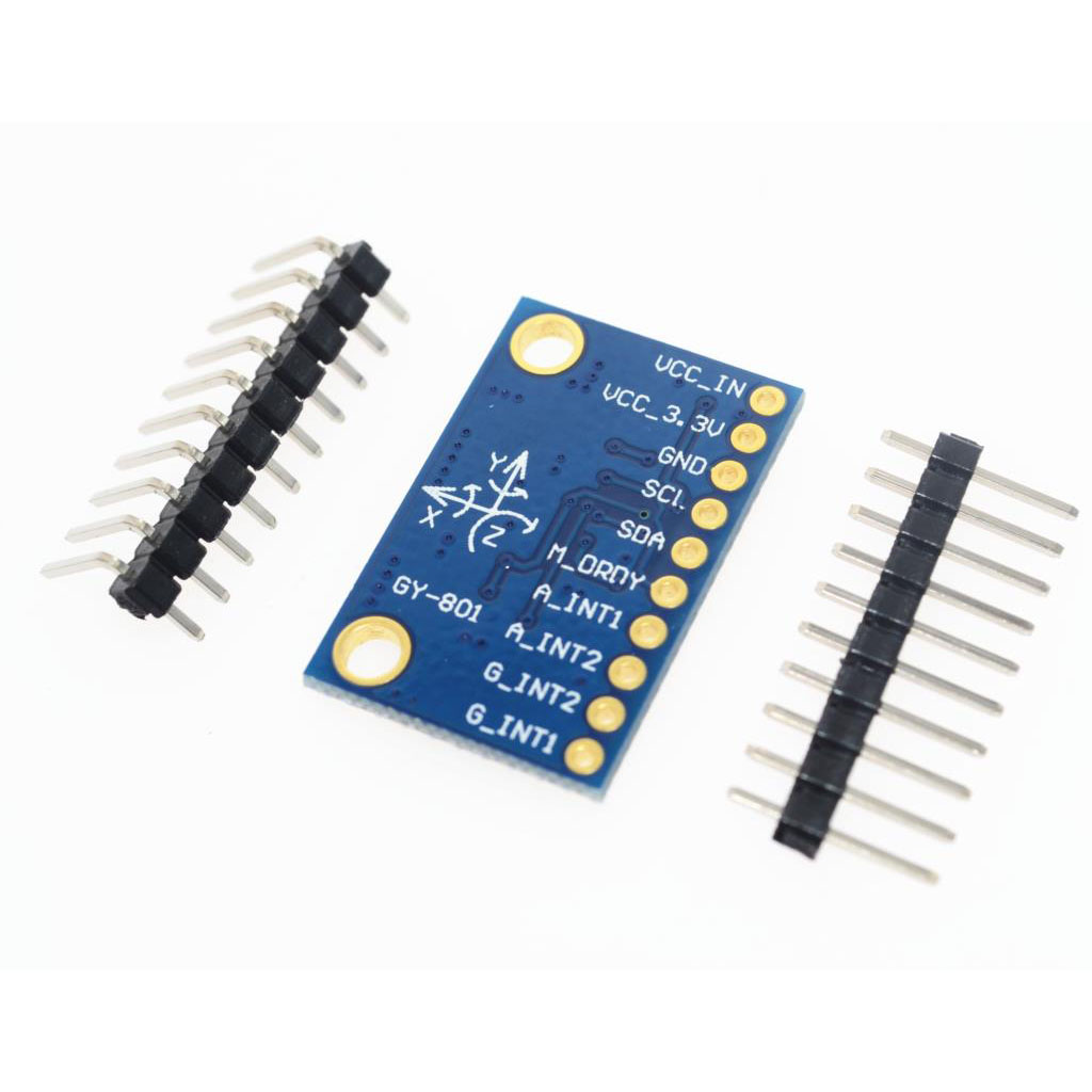
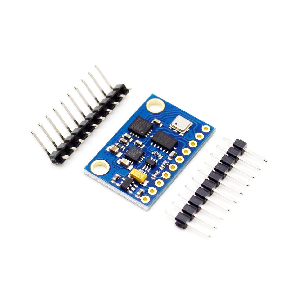
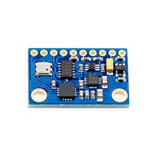
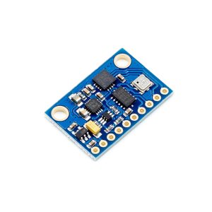
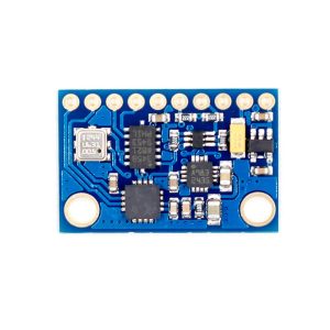
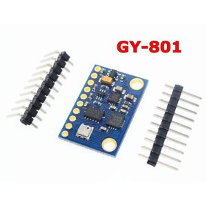
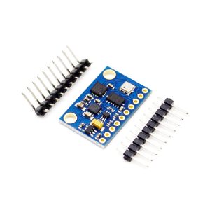
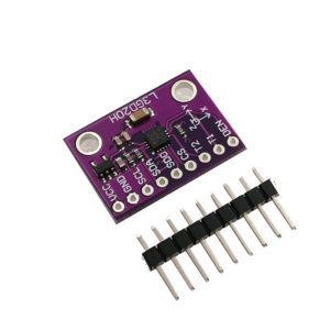
The GY-801 10DOF IMU Module is a comprehensive 9-axis motion tracking board that integrates five high-performance sensors on a single compact PCB. It combines a 3-axis gyroscope, a 3-axis accelerometer, a 3-axis magnetometer, and a barometric pressure sensor, providing a complete solution for applications requiring orientation sensing, motion tracking, and altitude measurement .
“10DOF” (Degrees of Freedom) refers to the combined sensing capabilities of the module:
-
3 axes of angular velocity (gyroscope)
-
3 axes of linear acceleration (accelerometer)
-
3 axes of magnetic field (magnetometer/compass)
-
1 barometric pressure channel (altitude)
This module is widely used in drones (UAVs), robotics, virtual reality systems, gaming controllers, GPS navigation systems, and inertial measurement units (IMUs). All sensors communicate via the I2C protocol, requiring only 2 data lines (SDA and SCL) to connect to your microcontroller .
Sensor Components
L3G4200D – 3‑Axis Gyroscope
-
Measures angular velocity (rate of rotation) around X, Y, and Z axes
-
User‑selectable full scales: ±250, ±500, or ±2000 degrees per second (dps)
-
16‑bit digital output with built‑in temperature sensor for drift compensation
ADXL345 – 3‑Axis Accelerometer
-
Measures linear acceleration (including gravity) on X, Y, and Z axes
-
Selectable ranges: ±2g, ±4g, ±8g, ±16g
-
13‑bit resolution (4 mg/LSB) – capable of detecting inclination changes as small as 0.25°
HMC5883L / MMC5883MA – 3‑Axis Magnetometer
-
Measures the Earth’s magnetic field for compass heading
-
12‑bit ADC with 1° to 2° heading accuracy
-
Integral degaussing straps and offset cancellation
BMP085 / BMP180 – Barometric Pressure & Temperature Sensor
-
Measures atmospheric pressure (300 to 1100 hPa) and temperature
-
Absolute accuracy down to 0.03 hPa
-
Altitude resolution of approximately 0.25 meters
Key Features
-
9‑Axis Motion Tracking: Gyroscope + accelerometer + magnetometer provides full 3D orientation sensing (yaw, pitch, roll)
-
Altitude & Weather Sensing: Barometric pressure sensor adds altitude measurement and pressure trend detection
-
Single I2C Interface: All sensors share the same I2C bus – only 2 pins (SDA, SCL) are needed
-
Wide Voltage Compatibility: Operates from 3V to 5V, compatible with both 3.3V and 5V microcontrollers
-
Built‑in Sensor Fusion Ready: Sensor data can be combined using algorithms like Madgwick or Mahony filters for stable orientation estimation
-
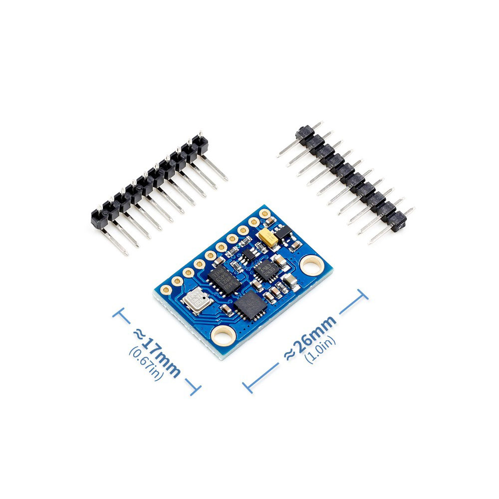
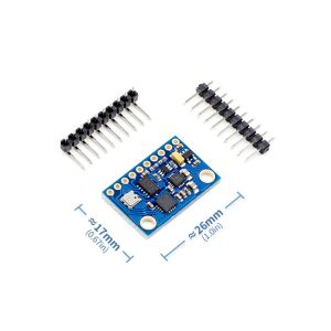
Compact Size: Small form factor (approx. 25x17mm) for easy integration into drones and robots
Technical Specifications
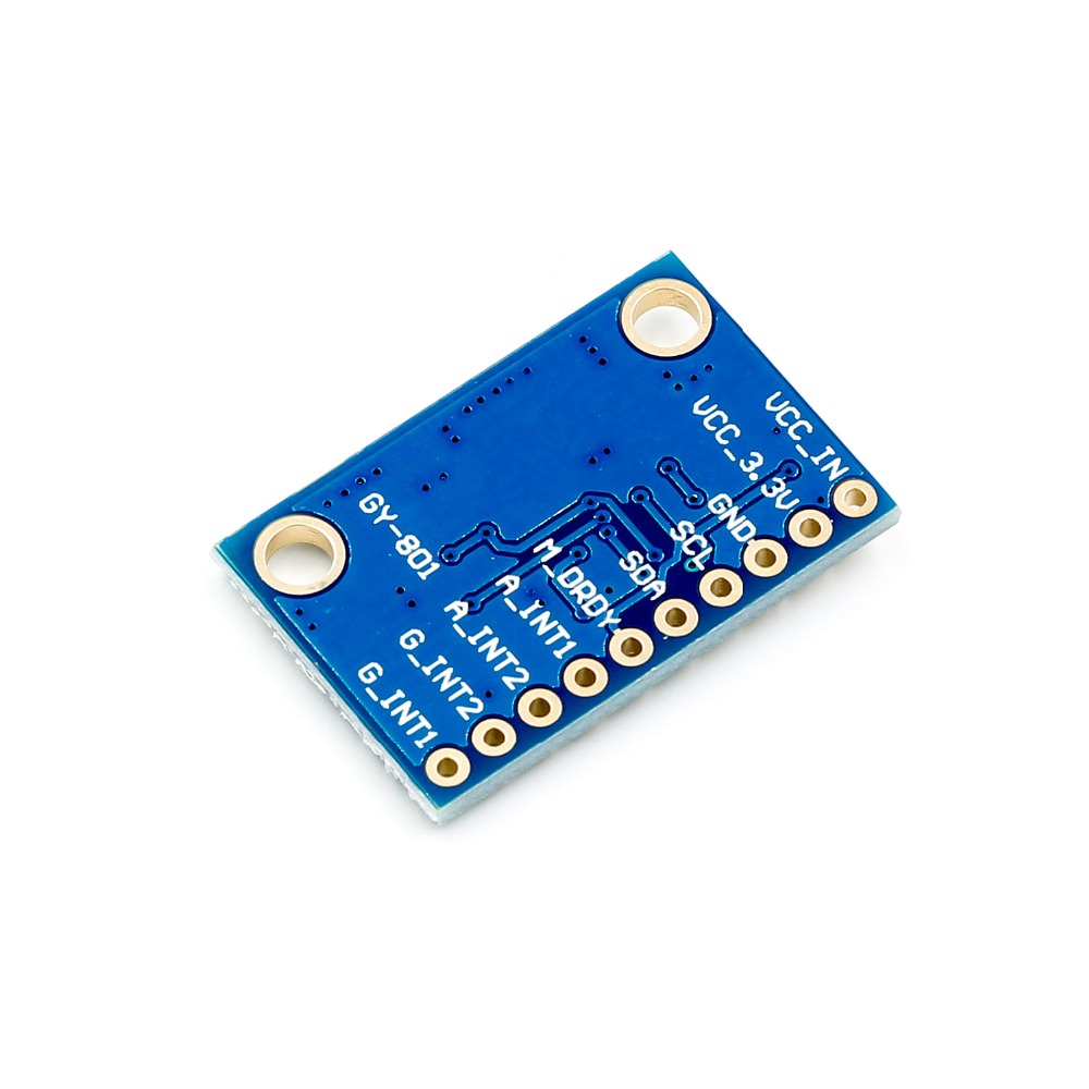
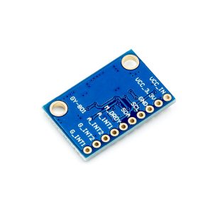
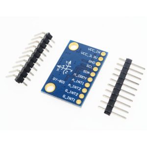
Pinout & Connection Guide
Pin Definitions
Wiring to Arduino Uno
Note: Interrupt pins (A_INT, G_INT, M_DRDY) are optional – connect only if needed for your application.
Usage Guide
Sensor Fusion: Why Combine Multiple Sensors?
Each sensor type has strengths and weaknesses. Sensor fusion combines them for accurate and stable orientation:
-
Accelerometer: Measures gravity – excellent for tilt (pitch/roll) but susceptible to linear acceleration noise.
-
Gyroscope: Measures rotation rate – stable over short periods but drifts over time.
-
Magnetometer: Measures magnetic north – provides absolute yaw reference but affected by magnetic interference.
By combining these using algorithms like Madgwick or Mahony filters, you get smooth, accurate, drift‑free orientation (yaw, pitch, roll).
Software Setup (Arduino IDE)
Step 1: Install Required Libraries
Install the following libraries via Library Manager:
Step 2: Basic Sensor Initialization Code
GY-801 10DOF IMU – Basic Sensor Initialization
*/
#include <Wire.h>
#include <Adafruit_Sensor.h>
#include <Adafruit_ADXL345_U.h>
#include <Adafruit_HMC5883_U.h>
#include <Adafruit_BMP085_U.h>
#include <L3G4200D.h>
Adafruit_ADXL345_Unified accel = Adafruit_ADXL345_Unified(12345);
Adafruit_HMC5883_Unified mag = Adafruit_HMC5883_Unified(12345);
Adafruit_BMP085_Unified bmp = Adafruit_BMP085_Unified(10085);
L3G4200D gyro;
void setup() {
Serial.begin(9600);
Wire.begin();
if(!accel.begin()) {
Serial.println("ADXL345 not found!");
while(1);
}
accel.setRange(ADXL345_RANGE_2_G);
if(!mag.begin()) {
Serial.println("HMC5883L not found!");
while(1);
}
if(!bmp.begin()) {
Serial.println("BMP085 not found!");
while(1);
}
gyro.init();
gyro.setFullScale(L3G4200D_FULLSCALE_2000);
Serial.println("GY-801 Sensors Ready");
}
Step 3: Reading All Sensors
void loop() {
sensors_event_t accelEvent, magEvent;
sensors_vec_t orientation;
accel.getEvent(&accelEvent);
Serial.print("Accel X: "); Serial.print(accelEvent.acceleration.x);
Serial.print(" Y: "); Serial.print(accelEvent.acceleration.y);
Serial.print(" Z: "); Serial.println(accelEvent.acceleration.z);
mag.getEvent(&magEvent);
float heading = atan2(magEvent.magnetic.y, magEvent.magnetic.x) * 180/PI;
if(heading < 0) heading += 360;
Serial.print("Heading: "); Serial.println(heading);
bmp.getEvent(&bmpEvent);
float altitude = bmp.pressureToAltitude(SENSORS_PRESSURE_SEALEVELHPA,
bmpEvent.pressure);
Serial.print("Altitude: "); Serial.println(altitude);
delay(500);
}
Q: How accurate is the altitude measurement?
The BMP085 can achieve altitude resolution of approximately 0.25 meters (8 inches) in ultra-high resolution mode . However, absolute accuracy depends on proper calibration with local sea-level pressure. For relative altitude changes (e.g., climbing stairs), the sensor is extremely precise.
Q: What is the difference between GY-65 and BMP180/BMP280 sensors?
The GY-65 uses the BMP085 sensor, which is an older but still capable sensor. The BMP180 and BMP280 offer improved specifications (lower noise, wider range) but the BMP085 remains a cost-effective choice for many altitude and weather applications. The GY-65 module is widely available and well-supported by libraries .
Q: Can I use this sensor with 5V logic microcontrollers like Arduino Uno?
Yes. The GY-65 module is both 3.3V and 5V compatible, so it can be used directly with 5V Arduinos without level shifters .
Q: What is the default I²C address of the GY-65 module?
The BMP085 has a fixed I²C address of 0x77 (119 decimal) .
Q: Why is my module not detected on the I²C bus?
Common issues:
-
Wiring: Verify VCC, GND, SCL, and SDA connections
-
Pull-up resistors: Ensure 4.7kΩ pull-ups are present on SCL and SDA lines
-
Power: Ensure your power supply can provide adequate current
-
Library: Verify the correct library is installed
Q: How do I improve altitude reading stability?
For stable altitude readings:
-
Use ultra-high resolution mode (OSS=3) for maximum precision
-
Apply a moving average filter to smooth readings
-
Allow the sensor to warm up for a few minutes before critical measurements
-
Protect the sensor from direct airflow (wind)
-
Re-calibrate the sea-level pressure reference when moving to different locations
Q: What oversampling setting should I use?
The choice depends on your application:
-
OSS=0 (Ultra-Low Power): Battery-powered, low-power applications
-
OSS=1 (Standard): General purpose, default setting
-
OSS=2 (High Resolution): Higher accuracy needs
-
OSS=3 (Ultra-High Resolution): Maximum precision (0.25m altitude resolution)
Q: Do I need to calibrate the sensor?
No. The BMP085 sensor is factory-calibrated, and the 11 calibration coefficients are stored in the sensor’s internal E²PROM. Your library will automatically read these coefficients and use them to convert raw ADC readings to accurate pressure and temperature values. No user calibration is required .
Q: Is the GY-65 suitable for use in drones or UAVs?
The BMP085 works well for altitude hold in drones, but it has a slower update rate than newer sensors like the BMP280 or MS5611. For basic altitude stabilization, it is sufficient, but for acrobatic or high-speed flight, a faster sensor is recommended.
Q: What is the power consumption in different modes?
The sensor is very power-efficient:
-
Active mode (converting): 5 µA typical
-
Standby mode: 0.1 µA
-
For battery-powered applications, place the sensor in standby between readings to conserve power