Product Overview
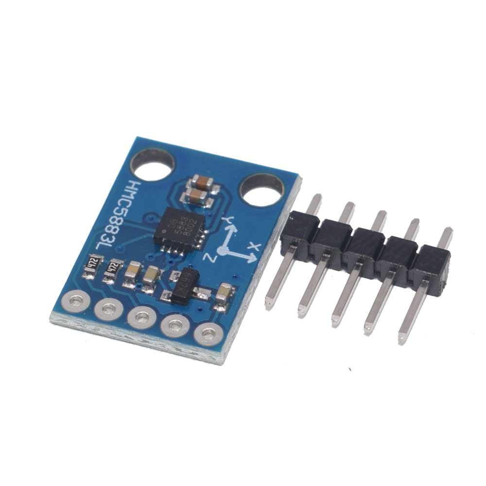
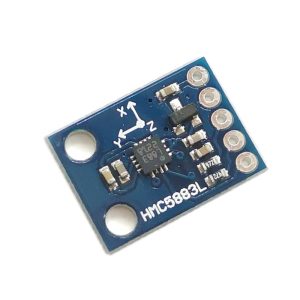
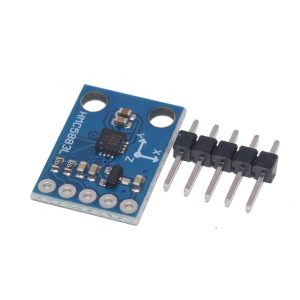
The GY-273 HMC5883L 3-Axis Magnetic Field Sensor Module is a compact, high-precision electronic compass module designed for measuring magnetic fields and determining orientation in space . Based on the Honeywell HMC5883L IC, this module provides accurate 3-axis magnetometry, making it an essential component for navigation systems, robotics, and various other applications requiring precise directional data .
The HMC5883L integrates Honeywell’s advanced Anisotropic Magnetoresistive (AMR) technology, which offers superior sensitivity and linearity compared to other magnetic sensor technologies . The chip features state-of-the-art, high-resolution magneto-resistive sensors combined with an ASIC containing amplification, automatic degaussing strap drivers, offset cancellation, and a 12-bit ADC . This integration enables compass heading accuracy of 1° to 2° .
Communication with the module is achieved via the simple I2C interface, requiring only two data lines (SDA and SCL) to connect to your microcontroller . The module operates on a wide voltage range of 3V to 5V, making it directly compatible with both 3.3V systems (ESP32, ESP8266, Raspberry Pi) and 5V systems (Arduino) .
The GY-273 module is particularly valued for its compact size (approximately 14×13×3.5mm), low power consumption (100µA typical), and ability to measure magnetic fields ranging from milli-gauss to ±8 Gauss . It features a Data Ready (DRDY) pin that can be used to trigger data reading only when new measurements are available, optimizing code efficiency .
Key Features
-
3-Axis Magnetic Field Sensing: Measures magnetic field strength on X, Y, and Z axes simultaneously for full 3D orientation detection
-
HMC5883L Chipset: Honeywell’s high-performance magneto-resistive sensor with integrated 12-bit ADC and ASIC
-
I2C Digital Interface: Simple 2-wire communication (SDA, SCL) uses only two pins, saving valuable I/O resources
-
Wide Voltage Compatibility: Operates on 3V – 5V DC, compatible with both 3.3V (ESP32, Raspberry Pi) and 5V (Arduino) systems
-
Low Power Consumption: Consumes only 100 µA in active measurement mode, ideal for battery-powered applications
-
Adjustable Measurement Range: User-selectable full-scale range from ±1.3 to ±8 Gauss
-
High Output Data Rate: Maximum output rate of 160 Hz, suitable for real-time orientation tracking
-
Data Ready Interrupt (DRDY): Optional pin indicates when new measurement data is available
-
Compact Form Factor: Small PCB size (approx. 14mm × 13mm × 3.5mm) fits easily into space-constrained projects
-
1° to 2° Heading Accuracy: Provides reliable compass heading after proper calibration
Technical Specifications
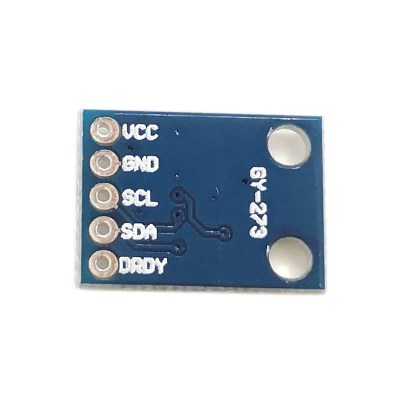
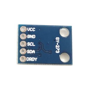
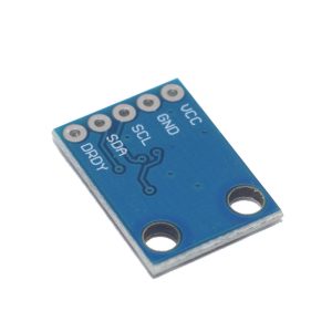
Pinout & Connection Guide
The GY-273 module features a 5-pin configuration, clearly labeled on the PCB .
Pin Definitions
Wiring Diagrams
For Arduino Uno / Nano:
For ESP32:
For ESP8266 (NodeMCU):
Theory of Operation
How a Magnetometer Works
The HMC5883L uses Anisotropic Magneto-Resistive (AMR) sensors – material that changes its electrical resistance in response to an external magnetic field . A bridge circuit measures these resistance changes, and the on-chip 12-bit ADC converts them to digital values. By measuring the magnetic field in three orthogonal axes (X, Y, Z), the Earth’s magnetic field vector can be determined, and the direction to magnetic north can be calculated .
Calculating Heading (Azimuth)
For a sensor held horizontally (parallel to the ground), the heading (azimuth) in degrees is calculated as:
heading = atan2(Y, X) × (180 / π)
Where:
If heading is negative, add 360° to get a result in the 0°–360° range .
Important: This formula gives magnetic north. To obtain true north, you must apply the magnetic declination (variation) for your geographic location .
Raw Data Interpretation
The 12-bit ADC outputs values ranging from -2048 to 2047. The measured magnetic field in Gauss is calculated as: field = raw_value × (gain / 2048), where gain is the selected sensitivity (e.g., 1090 LSB/Gauss for the ±1.3G range).
Usage Guide
Software Setup (Arduino IDE)
Step 1: Install Required Libraries
The easiest way to use the HMC5883L is with the Adafruit_HMC5883_Unified library.
-
Open Arduino IDE → Sketch → Include Library → Manage Libraries
-
Search for “Adafruit HMC5883”
-
Install the library by Adafruit (this will also install the Adafruit Sensor and BusIO libraries)
Step 2: Basic Test Sketch
GY-273 HMC5883L Compass Basic Read Example
*/
#include <Wire.h>
#include <Adafruit_Sensor.h>
#include <Adafruit_HMC5883_U.h>
Adafruit_HMC5883_Unified mag = Adafruit_HMC5883_Unified(12345);
void setup() {
Serial.begin(9600);
if (!mag.begin()) {
Serial.println("HMC5883L sensor not found! Check wiring.");
while (1);
}
mag.setRange(HMC5883L_RANGE_1_3GA);
mag.setMeasurementMode(HMC5883L_CONTINUOUS);
mag.setDataRate(HMC5883L_DATARATE_15_HZ);
Serial.println("GY-273 HMC5883L Ready");
Serial.println("-----------------------------");
}
void loop() {
sensors_event_t event;
mag.getEvent(&event);
float x = event.magnetic.x / 100.0;
float y = event.magnetic.y / 100.0;
float z = event.magnetic.z / 100.0;
float heading = atan2(y, x) * 180 / PI;
if (heading < 0) heading += 360;
Serial.print("X: "); Serial.print(x);
Serial.print(" G, Y: "); Serial.print(y);
Serial.print(" G, Z: "); Serial.print(z);
Serial.print(" G | Heading: ");
Serial.println(heading);
delay(100);
}
Step 3: Manual I2C Implementation (No Library)
GY-273 Manual I2C Read Example
*/
#include <Wire.h>
#define HMC5883L_ADDR 0x1E
#define CONFIG_A_REG 0x00
#define CONFIG_B_REG 0x01
#define MODE_REG 0x02
#define DATA_REG_BEGIN 0x03
void setup() {
Serial.begin(9600);
Wire.begin();
Wire.beginTransmission(HMC5883L_ADDR);
Wire.write(CONFIG_A_REG);
Wire.write(0x70);
Wire.endTransmission();
Wire.beginTransmission(HMC5883L_ADDR);
Wire.write(CONFIG_B_REG);
Wire.write(0xA0);
Wire.endTransmission();
Wire.beginTransmission(HMC5883L_ADDR);
Wire.write(MODE_REG);
Wire.write(0x00);
Wire.endTransmission();
Serial.println("GY-273 Manual Mode Ready");
}
void loop() {
Wire.beginTransmission(HMC5883L_ADDR);
Wire.write(DATA_REG_BEGIN);
Wire.endTransmission();
Wire.requestFrom(HMC5883L_ADDR, 6);
if (Wire.available() >= 6) {
int16_t x = Wire.read() << 8 | Wire.read();
int16_t z = Wire.read() << 8 | Wire.read();
int16_t y = Wire.read() << 8 | Wire.read();
float fx = x / 1090.0;
float fy = y / 1090.0;
float fz = z / 1090.0;
float heading = atan2(fy, fx) * 180 / PI;
if (heading < 0) heading += 360;
Serial.print("Heading: ");
Serial.println(heading);
}
delay(100);
}
Calibration for Accurate Heading
The magnetometer measures the Earth’s magnetic field, but nearby electronics (motors, wires, batteries) introduce hard-iron distortions. Calibration is essential for accurate heading .
Simple Hard-Iron Offset Calibration
-
Place the sensor in a fixed location
-
Rotate the sensor 360° in the horizontal plane
-
Record the minimum and maximum raw values for X and Y axes
-
Calculate offsets:
X_offset = (X_max + X_min) / 2
Y_offset = (Y_max + Y_min) / 2
-
Apply offsets to all future readings:
X_cal = X_raw - X_offset
Y_cal = Y_raw - Y_offset
-
Recalculate heading using calibrated values
Using the DRDY Pin (Optional)
The DRDY pin pulses LOW for 250µs when new measurement data is ready . This can be used to trigger an interrupt in your microcontroller:
attachInterrupt(digitalPinToInterrupt(DRDY_PIN), dataReadyISR, FALLING);
Q: What is the default I2C address of the GY-273 module?
The default 7-bit I2C address is 0x1E (8-bit write address 0x3C, read address 0x3D) . This address is fixed, so only one HMC5883L can be used per I2C bus.
Q: Can I use the GY-273 with a 5V Arduino directly?
Yes. The module operates on 3V–5V and is directly compatible with both 3.3V and 5V systems. Connect VCC to 5V and SDA/SCL directly to the I2C pins .
Q: Why is my compass not showing the correct heading?
The most common cause is lack of calibration. Nearby electronics create magnetic interference that must be compensated for using hard-iron calibration. Rotate the sensor 360° to collect min/max values and apply the offsets . Also, ensure you are not near large metal objects or strong magnetic sources.
Q: Can I use this module with an ESP32 or ESP8266?
Yes. Connect VCC to 3.3V and SDA/SCL to the appropriate I2C pins (GPIO21/22 for ESP32, GPIO4/5 for ESP8266). The Adafruit library works on these platforms.
Q: Does the GY-273 measure magnetic north or true north?
The HMC5883L measures magnetic north. To obtain true north, you must apply the magnetic declination (variation) for your geographic location .
Q: What is the DRDY pin used for?
The DRDY (Data Ready) pin pulses LOW for 250µs when new measurement data is available . This can be connected to a microcontroller interrupt pin to trigger data reading only when new data is ready.
Q: What is the accuracy of the heading measurement?
After proper calibration, the HMC5883L can achieve heading accuracy of 1° to 2° . For best results, calibrate the sensor in the final installation environment.
Q: How do I convert the raw output values to Gauss?
Divide the raw ADC value by the gain for your selected range. For the ±1.3 Gauss range, the gain is 1090 LSB/Gauss, so: Gauss = raw_value / 1090.
Q: What is the difference between the HMC5883L and the QMC5883L?
The QMC5883L is a compatible alternative with a different I2C address (0x0D). Some modules may ship with the QMC5883L instead. If your compass is not responding at address 0x1E, try address 0x0D.
Q: Why am I not reading any data from the sensor?
Common issues:
-
I2C wiring: Verify VCC, GND, SCL, and SDA connections
-
Pull-up resistors: The I2C bus requires pull-up resistors (typically 4.7kΩ)
-
Sensor initialization: Ensure you are setting the configuration registers correctly
-
Address: Verify the device address using an I2C scanner sketch
-
Power: Ensure your power supply can deliver adequate current