Product Overview
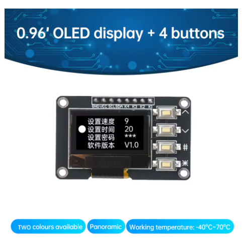
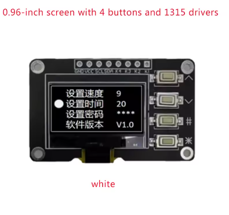
The 0.96 Inch OLED Display with 4×4 Matrix Keypad is an all-in-one human-machine interface (HMI) solution specifically designed for makers, engineers, and embedded developers . This innovative module combines a crisp White OLED display with a responsive 16-button tactile keypad, allowing you to build interactive control panels, menu systems, and data entry interfaces without the mess of complex wiring.
Traditionally, connecting a 4×4 matrix keypad requires 8 individual digital I/O pins, which consumes significant resources on your microcontroller . This module solves that problem by integrating an I2C interface for both the display and the keypad. Both components share the same two-wire bus (SDA/SCL), saving valuable pins for other sensors and actuators .
At the heart of the display is the advanced SSD1315 driver IC, which is a drop-in upgrade from the classic SSD1306. It features a built-in 128 x 64-bit SRAM buffer, supports 256-step contrast control, and ensures a wide -40°C to 85°C operating temperature range . Whether you are creating a smart home thermostat, a retro gaming console, or a data logging terminal, this module provides the perfect balance of visual feedback and input control.
Key Features
-
Integrated Design: Combines a 0.96″ White OLED and a 4×4 Matrix Keypad on a single compact PCB.
-
I2C Communication: Uses only 2 pins (SDA/SCL) to control the display and read the keyboard, leaving your microcontroller’s other pins free .
-
High-Contrast Display: 128×64 pixel resolution with bright white graphics on a true black background, offering excellent visibility and wide viewing angles .
-
Advanced SSD1315 Driver: Features a built-in 128×64-bit SRAM buffer, internal oscillator, and charge pump, reducing external component requirements .
-
Tactile Keypad: 16 physical buttons arranged in a 4×4 matrix provide responsive tactile feedback for robust user input .
-
Wide Compatibility: Fully compatible with Arduino, ESP32, ESP8266, Raspberry Pi, and STM32 via the I2C protocol .
-
Durable & Reliable: Industrial-grade design with a wide operating temperature range of -40°C to 85°C .
-
Low Power Consumption: OLED technology consumes power only on lit pixels, making it ideal for battery-powered applications .
Technical Specifications
Pinout & Usage Guide
Hardware Connection
Integrating the module is straightforward. Connect the following pins to your microcontroller (e.g., Arduino Uno).
Note: The INT (Interrupt) pin on the keypad is optional. If connected, it can detect key presses without continuously polling the bus .
Software & Library Support
To get started, you need libraries for the display and the keypad. For Arduino IDE users, install the following libraries via the Library Manager:
-
Adafruit GFX Library (Core graphics library).
-
Adafruit SSD1306 (Driver for the display – works with SSD1315).
-
Adafruit Keypad (Library to handle the matrix keypad logic) .
By default, the I2C address for these modules is usually 0x3C. If you run into issues, run an “I2C Scanner” sketch to verify the address.
Example Code Snippet (Concept)
The following pseudo-code demonstrates the high-level logic of reading a key press and displaying it on the screen.
#include <Wire.h>
#include <Adafruit_GFX.h>
#include <Adafruit_SSD1306.h>
#include <Adafruit_Keypad.h>
#define SCREEN_WIDTH 128
#define SCREEN_HEIGHT 64
#define OLED_RESET -1
Adafruit_SSD1306 display(SCREEN_WIDTH, SCREEN_HEIGHT, &Wire, OLED_RESET);
const byte ROWS = 4, COLS = 4;
char keys[ROWS][COLS] = {{'1','2','3','A'},{'4','5','6','B'},{'7','8','9','C'},{'*','0','#','D'}};
byte rowPins[ROWS] = {1, 2, 3, 4};
byte colPins[COLS] = {5, 6, 7, 8};
Adafruit_Keypad customKeypad = Adafruit_Keypad( makeKeymap(keys), rowPins, colPins, ROWS, COLS);
void setup() {
display.begin(SSD1306_SWITCHCAPVCC, 0x3C);
display.display();
customKeypad.begin();
}
void loop() {
customKeypad.tick();
while(customKeypad.available()){
keypadEvent e = customKeypad.read();
if (e.bit.EVENT == KEY_JUST_PRESSED) {
display.clearDisplay();
display.println(e.bit.KEY);
display.display();
}
}
}
Q: Does this module require a separate driver board to work?
No, it is a self-contained module. The SSD1315 driver chip is integrated directly onto the display board, and the I2C interface is built-in for the keypad .
Q: How many pins does it take to run this module?
It only requires 4 pins (VCC, GND, SCL, SDA). This is the main advantage of the I2C design, saving you 8+ pins compared to a standard matrix keypad .
Q: Does this module work with 5V logic (like Arduino Uno)?
Yes, the module is rated for 5V operation. You can connect the VCC directly to the 5V pin of your Arduino and the SDA/SCL lines to the analog pins (A4/A5) .
Q: Which library works best with the SSD1315 chip?
The standard Adafruit SSD1306 library is fully compatible with the SSD1315 . You may also use the U8g2 library, though it has a steeper learning curve.
Q: What is the difference between SSD1306 and SSD1315?
The SSD1315 is a newer generation driver. It features an embedded 128×64-bit SRAM, supports a wider operating temperature (-40°C to 85°C), and maintains compatibility with the SSD1306 command set, allowing you to use the same software libraries .
Q: The 4x4 keypad has 16 buttons. Can I run out of memory on an Arduino Uno?
The Adafruit Keypad library is optimized and handles the 16 keys efficiently. An Arduino Uno has ample memory to run this display combined with the keypad .
Q: How do I know which I2C address my display uses?
Most default to 0x3C. You can run an “I2C Scanner” sketch (available in the Arduino Examples) to detect the exact address of your device .
Q: Can I use this for a battery-powered project?
Yes, OLED displays are power-efficient because they do not require a backlight. Power consumption is proportional to the number of white pixels displayed, making it suitable for portable devices .
Q: Is the keypad membrane or mechanical?
It is a tactile membrane keypad, offering a good balance between durability and low profile
Q: What happens if I connect the module to 3.3V instead of 5V?
The module supports both. If you are using an ESP32 or Raspberry Pi (3.3V logic), connect VCC to 3.3V. If using an Arduino Uno (5V logic), connect VCC to 5V .