Product Overview
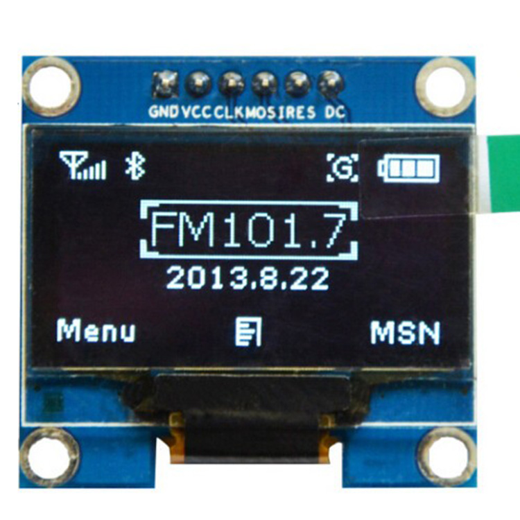
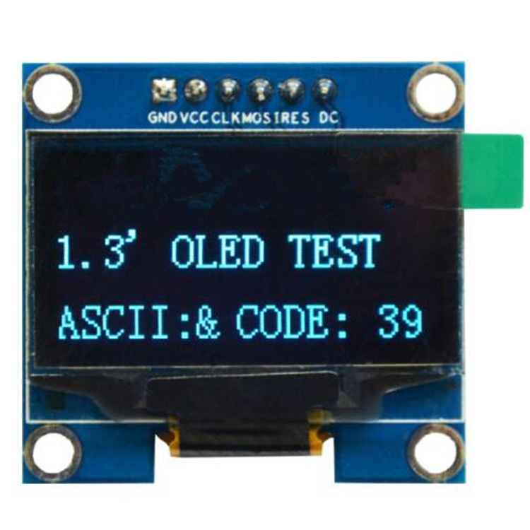
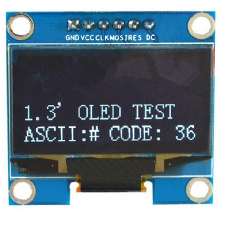
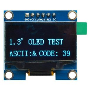
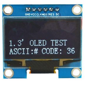
The 1.3-inch White SPI OLED Display Module is a compact, high-contrast monochrome screen designed for embedded applications requiring crisp visual output and fast refresh rates. Powered by the SH1106 driver IC and featuring a sharp 128×64 pixel resolution, this display delivers clean white text, detailed graphics, and custom icons on a true black background .
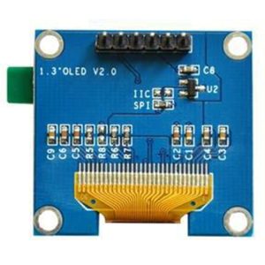
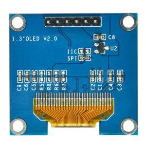
This 6-pin SPI version offers significantly faster data transfer compared to I2C versions, making it ideal for applications requiring smooth animations, frequent screen updates, or displaying large amounts of data. The dedicated RES (Reset) and DC (Data/Command) pins provide full independent control of the display, ensuring reliable operation .
Unlike traditional LCDs that require a power-hungry backlight, OLED (Organic Light Emitting Diode) technology allows each pixel to emit its own light. Inactive pixels are completely off, resulting in true blacks, exceptional contrast (2000:1 typical), and >160° viewing angles – ensuring the display remains readable from virtually any angle .
With support for both 3.3V and 5V power supply (note: logic pins are 3.3V only), this module works with Arduino (with level shifters), ESP32, ESP8266, STM32, Raspberry Pi, and most other development boards .
Key Features
-
1.3-Inch Active Area: 29.42mm × 14.7mm display area offers better readability than 0.96″ screens while maintaining 128×64 resolution
-
128×64 Pixel Resolution: High-definition display capable of showing detailed graphics, bitmaps, custom icons, and up to 8 lines of text
-
White Monochrome OLED: Clean white pixels on true black background provide excellent contrast and professional appearance
-
SH1106 Driver IC: Industry-standard controller with built-in 132×64-bit SRAM buffer, designed specifically for 128×64 displays
-
SPI Interface (fast): 6-pin SPI communication provides faster data transfer than I2C – ideal for animations and frequent screen updates
-
Independent Control Pins: Dedicated RES (Reset) and DC (Data/Command) pins for full display control
-
Wide Voltage Compatibility: Accepts 3.3V–5.5V power supply (VCC) – compatible with both 5V and 3.3V systems
-
⚠️ Logic Level Warning: SPI logic pins (SCL/CLK, SDA/MOSI, RES, DC) are 3.3V only – use level shifters with 5V microcontrollers
-
Ultra-Low Power Consumption: Typical 40mA when fully lit; unlit pixels draw no power – ideal for battery-powered projects
-
Industrial Temperature Range: Rated for -40°C to +85°C, suitable for demanding environments
Technical Specifications
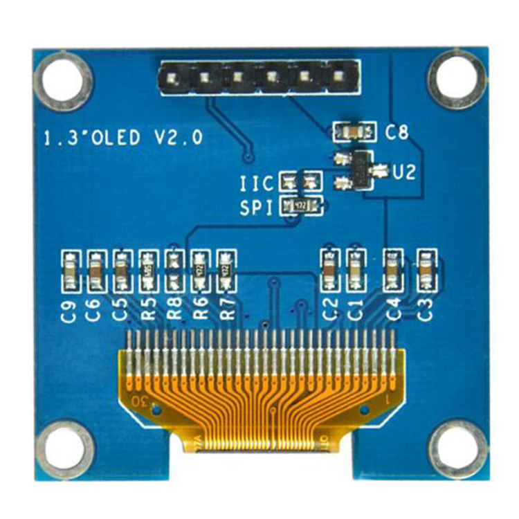
Pinout & Connection Guide
The 6-pin SPI interface requires 3.3V logic levels. ⚠️ Important: The MOS, CLK, RES, and DC pins are NOT 5V tolerant . When using 5V microcontrollers (Arduino Uno/Mega), you must use logic level shifters.
Some 6-pin modules omit the CS (Chip Select) pin – the display is always selected . For multi-device SPI buses, use the 7-pin version with CS.
Wiring Diagram (ESP32 – Direct Connection – No Level Shifters Needed)
Since ESP32 operates at 3.3V logic, no level shifters are required – connect directly:
ESP32          →    1.3" OLED Module
─────────────────────────────────────
3.3V           →    VCC
GND            →    GND
GPIO18 (SCK)   →    SCL (CLK)
GPIO23 (MOSI)  →    SDA (MOSI)
GPIO4          →    RES
GPIO2          →    DC
Wiring Diagram (Arduino Uno – Requires Level Shifters)
Arduino Uno uses 5V logic, which WILL DAMAGE the OLED’s logic pins. You must use 3.3V level shifters:
Arduino Uno      →    Level Shifter (3.3V side) →    OLED Module
─────────────────────────────────────────────────────────────────
5V (power)       →    HV (5V)                  →    (to VCC)
GND              →    GND (common)             →    GND
D13 (SCK)        →    HV1                      →    LV1 → SCL
D11 (MOSI)       →    HV2                      →    LV2 → SDA
D8               →    HV3                      →    LV3 → RES
D9               →    HV4                      →    LV4 → DC

VCC of OLED connects directly to 5V (power supply is 5V tolerant).
Alternative: Use a 3.3V Arduino Pro Mini or other 3.3V board to avoid level shifters entirely.
SH1106 Driver IC: Key Information
The SH1106 is a popular driver IC for monochrome OLED displays with several important characteristics :
Internal RAM (GDDRAM):
Communication Interfaces:
Onboard Charge Pump:
Internal Oscillator:
Usage Guide
Software Setup (Arduino IDE)
Step 1: Install Required Libraries
The U8g2 library is the most reliable choice for SH1106 SPI displays, offering excellent support and many font options .
-
Open Arduino IDE → Sketch → Include Library → Manage Libraries
-
Search for “U8g2” by Oliver Kraus
-
Click Install (U8g2 is widely tested and recommended for SH1106 displays)
Alternative Libraries:
Step 2: Basic Test Sketch (U8g2 Library – Hardware SPI)
For ESP32 / 3.3V boards (direct connection – no level shifters needed):
#include <Arduino.h>
#include <U8g2lib.h>
#include <SPI.h>
U8G2_SH1106_128X64_NONAME_1_4W_HW_SPI u8g2( U8G2_R0, 15, 2, 4);
void setup() {
u8g2.begin();
u8g2.enableUTF8Print();
u8g2.setFont(u8g2_font_ncenB08_tr);
u8g2.setDrawColor(1);
}
void loop() {
u8g2.firstPage();
do {
u8g2.drawStr(0, 15, "1.3 OLED");
u8g2.drawStr(0, 35, "128x64");
u8g2.drawStr(0, 55, "SH1106");
} while ( u8g2.nextPage() );
delay(1000);
}
Note: If your module has a CS (Chip Select) pin, include it in the constructor (4th parameter). For 6-pin modules without CS, the U8g2 library may require a dummy pin value.
Step 3: Alternative: Adafruit SH110X Library
#include <SPI.h>
#include <Wire.h>
#include <Adafruit_GFX.h>
#include <Adafruit_SH110X.h>
#define OLED_DC 2
#define OLED_CS 15
#define OLED_RESET 4
Adafruit_SH1106G display = Adafruit_SH1106G(128, 64, &SPI, OLED_DC, OLED_RESET, OLED_CS);
void setup() {
Serial.begin(9600);
if(!display.begin(0x3C, true)) {
Serial.println(F("SH1106 allocation failed"));
for(;;);
}
display.clearDisplay();
display.setTextSize(2);
display.setTextColor(SH110X_WHITE);
display.setCursor(10, 25);
display.println("1.3 OLED");
display.println("Ready!");
display.display();
}
void loop() {}
Raspberry Pi (Python) Setup
Enable SPI via raspi-config, then install required libraries:
sudo apt-get install python3-pip
pip3 install luma.oled
from luma.core.interface.serial import spi
from luma.oled.device import sh1106
from luma.core.render import canvas
serial = spi(port=0, device=0, gpio_DC=24, gpio_RST=25, gpio_CS=8)
device = sh1106(serial)
with canvas(device) as draw:
draw.rectangle(device.bounding_box, outline="white", fill="black")
draw.text((30, 20), "1.3 OLED", fill="white")
draw.text((30, 40), "SPI 128x64", fill="white")
Important Note: Enable Charge Pump
For proper operation, the SH1106’s internal charge pump must be enabled. Most libraries do this automatically, but if your display remains off, add this command in setup:
display.ssd1306_command(0x8D);
display.ssd1306_command(0x14);
Understanding the Display Buffer Workflow (U8g2)
U8g2 uses a page-buffered approach:
u8g2.firstPage();
do {
u8g2.drawStr(0, 20, "Hello");
} while ( u8g2.nextPage() );
This structure allows the same code to work on both full-buffer and low-memory devices .
Q: What is the difference between this 1.3" white SPI OLED and the 0.96" version?
The 1.3″ version has a larger active area (29.42mm × 14.7mm vs 21.74mm × 10.86mm) while maintaining the same 128×64 resolution, resulting in larger, more readable pixels . Additionally, the 1.3″ typically uses the SH1106 driver, while 0.96″ often uses SSD1306.
Q: Can I use an SSD1306 library with this SH1106 display?
Some SSD1306 libraries may work, but they may not handle the SH1106’s offset correctly (SH1106 has 132×64 internal RAM with a 2-pixel offset). For guaranteed compatibility, use libraries that explicitly support SH1106, such as U8g2 (recommended) or Adafruit SH110X .
Q: What is the advantage of SPI over I2C for this display?
SPI is significantly faster. Writing the full display buffer (1056 bytes) takes ~8.4ms at 1MHz SPI vs much longer over I2C . This makes SPI the right choice for animations, rapid screen updates, or real-time data dashboards.
Q: Why does this module have 6 pins while others have 7?
Some modules omit the CS (Chip Select) pin, tying it permanently LOW (display always selected) . This is fine for single-device SPI buses. For multi-device applications, use the 7-pin version with CS.
Q: How many characters can the display show?
With the default 8×8 pixel font, approximately 16 characters × 8 lines = 128 characters total. With larger fonts (e.g., 16×16 pixels), about 8 characters × 4 lines = 32 characters.
Q: What is the lifespan of the OLED display?
Rated lifespan is approximately 20,000-30,000 hours of continuous operation (about 2.5-3.5 years). Avoid displaying static images for extremely long periods to prevent uneven pixel wear (“burn-in”).
Q: Can I connect this display directly to a 5V Arduino (Uno, Mega, etc.)?
NO! The SPI logic pins (SCL, SDA/MOSI, RES, DC) are NOT 5V tolerant . Applying 5V directly to these pins will damage the display. However, the VCC power pin IS 5V tolerant (3.1V–5.5V) .
For 5V microcontrollers (Arduino Uno/Mega), you MUST:
-
Connect VCC to 5V (this is safe)
-
Use 3.3V logic level shifters on SCL, SDA, RES, and DC pins
-
OR use a 3.3V board (ESP32, Raspberry Pi, Arduino Pro Mini 3.3V) for direct connection
Q: Can I connect this display directly to ESP32 or Raspberry Pi?
YES – both ESP32 and Raspberry Pi use 3.3V logic, which matches the display’s requirements. Connect directly without level shifters .
Q: Can I power the display from 3.3V instead of 5V?
Yes. VCC accepts 3.1V–5.5V, so 3.3V power works perfectly and may simplify your wiring .
Q: How much current does the OLED display draw?
Power consumption depends on how many pixels are lit :
Q: Can I adjust the display brightness?
Yes. The SH1106 supports contrast adjustment through library commands. In U8g2, contrast can be set via u8g2.setContrast(value) where value ranges from 0 to 255.
Q: Why does my display stay blank after power-up?
Check these common issues:
-
Logic voltage mismatch – If using 5V Arduino, did you use level shifters on logic pins?
-
Wiring – Verify VCC power, GND connections
-
Library initialization – Ensure you’re using a SH1106-compatible library (U8g2 recommended)
-
Charge pump – The internal charge pump must be enabled (see example above)
-
SPI pins – Verify SCK and MOSI are connected to the correct pins
Q: Does this module have pull-up resistors?
No. SPI mode does not require pull-up resistors on CLK/MOSI lines. Leave them unconnected or use standard 4.7k-10kΩ resistors if noise is an issue.
Q: Can I use this display with Raspberry Pi?
Yes. Enable SPI via raspi-config, then use Python libraries like luma.oled or Adafruit_CircuitPython_SSD1306 (with SH1106 support). Connect VCC to 3.3V (Pin 1), GND to GND, and SPI pins accordingly.