Product Overview
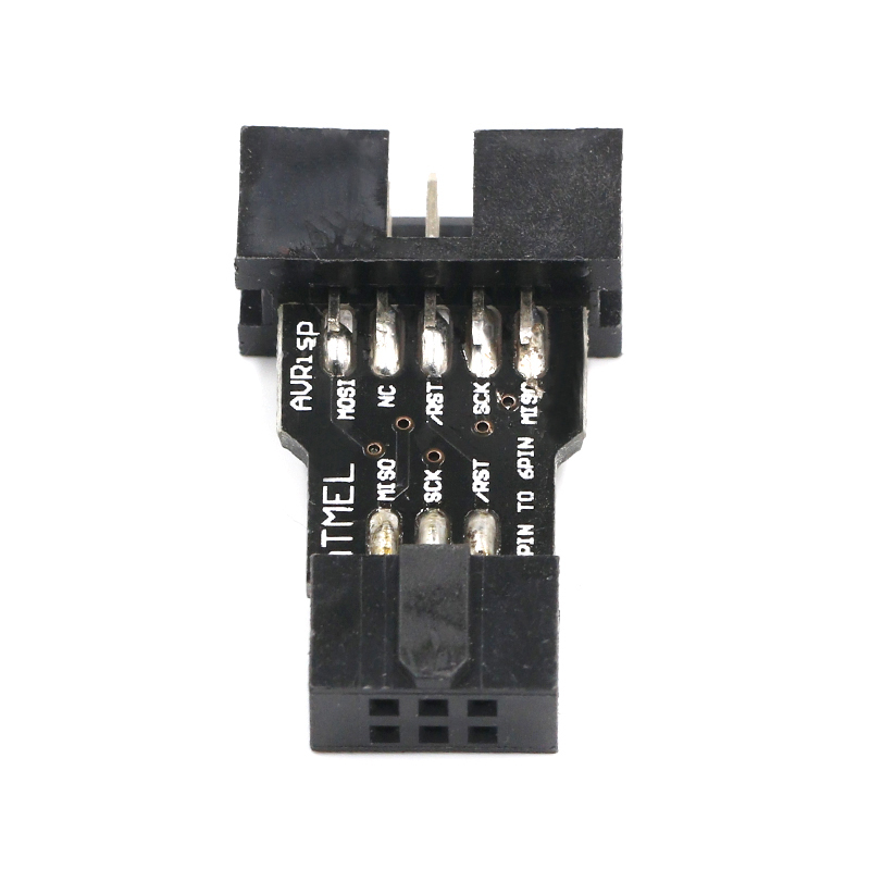
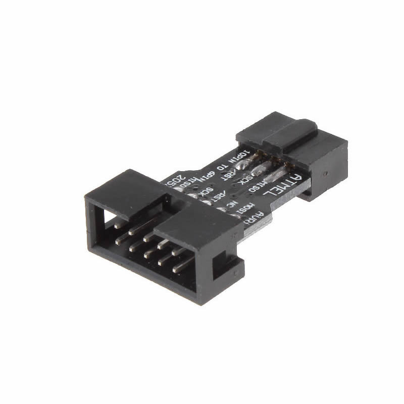
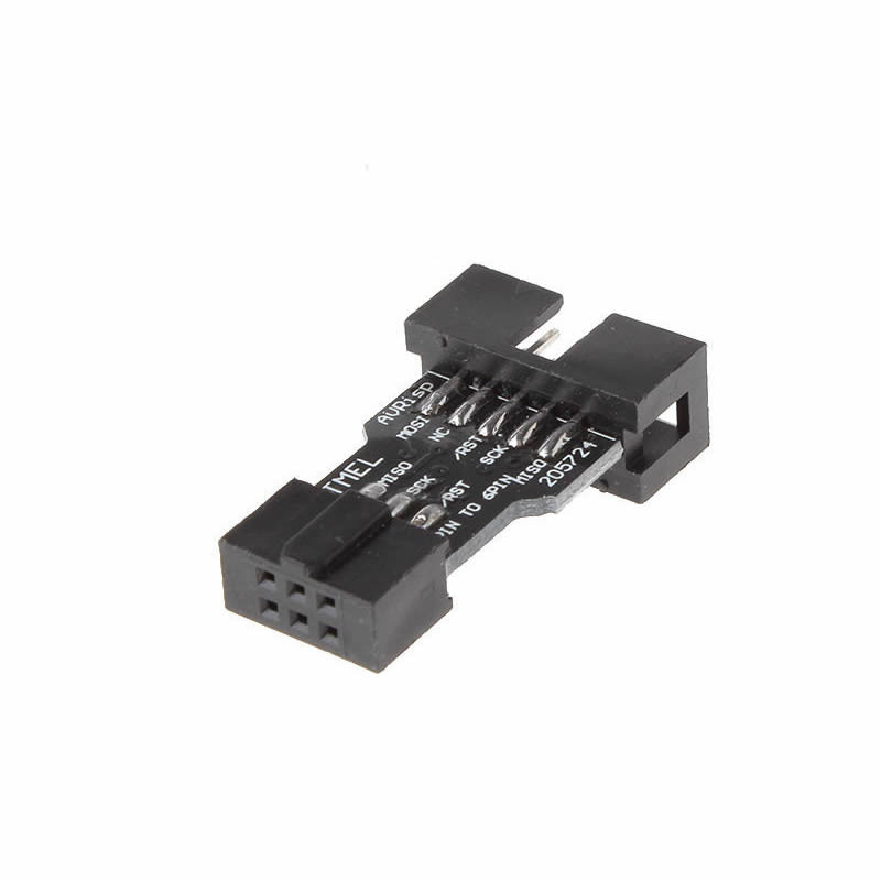
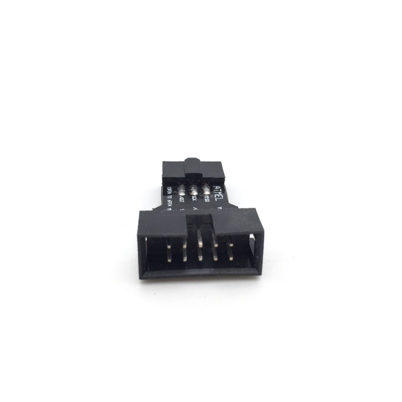
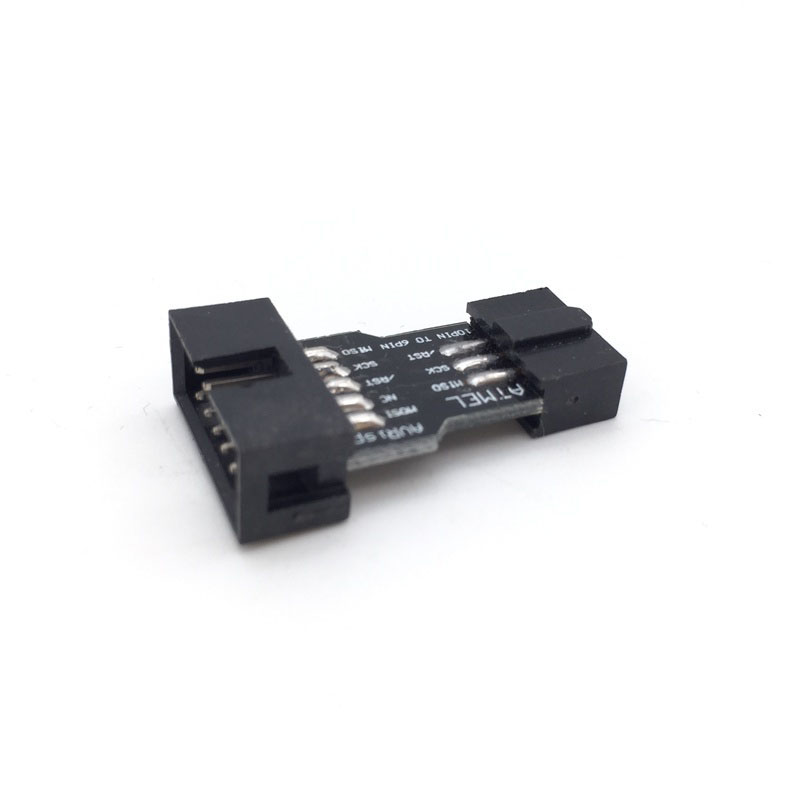
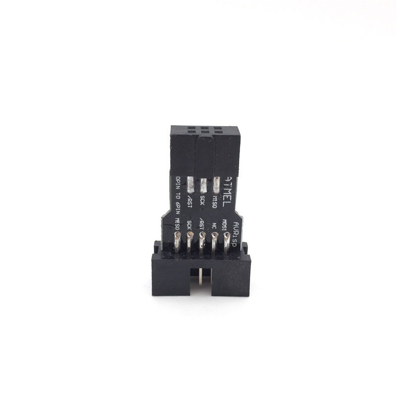
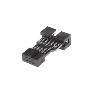
The 10 Pin to 6 Pin ISP Adapter Board is a compact, high-quality interface board that bridges the gap between standard 10-pin AVR programmers (like AVRISP, USBASP, STK500) and target boards that feature a 6-pin ISP (In-System Programming) header . This adapter eliminates the frustration of incompatible connectors, allowing you to use a single, versatile programmer across all your AVR and Arduino projects.
This 10-to-6 pin converter board is essential because the AVR programming ecosystem has two common physical connection standards. The 10-pin connector is the older “Atmel standard” found on many professional programmers and development boards, while the 6-pin connector is the compact, space-saving standard popularized by Arduino (on boards like the Uno, Nano, and Mega) and modern USBasp programmers .
With this adapter, there is no need to own two separate programmers or to perform complex rewiring. Simply plug the 10-pin IDC cable from your programmer into the adapter’s male header, and then connect a standard 6-pin cable from the adapter’s female header to your target device. All signal lines (MOSI, MISO, SCK, RESET, VCC, GND) are routed one-to-one in accordance with the official Atmel STK500 pinout specification, ensuring reliable communication and safe programming .
Key Features
-
Universal Compatibility: Bridges 10-pin AVRISP programmers (STK500, AVRISP mkII) to 6-pin ISP targets (Arduino, USBasp, etc.).
-
Standardized Pinout: Adheres to the official Atmel 10-pin and 6-pin ISP specifications for error-free signal routing.
-
Plug-and-Play: No soldering or configuration required; purely passive signal pass-through.
-
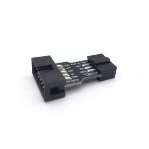
High-Quality PCB: 1.6mm thick FR4 board with clear silkscreen numbering for effortless pin identification .
-
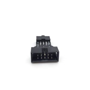
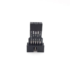
Secure Connections: Features a male (10-pin) header and a female (6-pin) header, both with a standard 2.54mm (0.1-inch) pitch.
-
Wide Support: Compatible with USBASP, USBISP, AVRISP MKII, STK500, and Arduino-as-ISP programmers .
-
Industrial Durability: Designed for repeated use with reinforced pin headers and a sturdy PCB.
-
Compact Size: Small footprint (approx. 34x20mm) allows easy integration into tight project enclosures .
Pinout & Signal Mapping
The adapter routes signals directly between the 10-pin and 6-pin headers. The standard signal mapping is as follows (Pin 1 indicator is usually marked with a triangle or a dot on the PCB):
Important Physical Note: On the target (6-pin) side, Pin 1 is typically marked with a square pad or a dot. Always align the notch on your 6-pin ISP cable with the adapter’s pin 1 indicator to ensure correct polarity .
Technical Specifications
Usage Guide
Required Components
-
1x 10-pin to 6-pin Adapter Board (this product)
-
1x 10-pin IDC ribbon cable (usually provided with your programmer)
-
1x 6-pin IDC to 6-pin IDC cable (or 6-pin female to female jumper wires)
Step-by-Step Connection
-
Attach to Programmer: Connect your programmer’s 10-pin IDC cable to the male header on the adapter. The shroud on the cable ensures it only goes on one way. Do not force it.
-
Connect to Target: Connect your 6-pin ISP cable (or jumper wires) from the female header on the adapter to the 6-pin ISP header on your target board (Arduino, AVR chip, etc.).
-
Verify Pin 1: Ensure that the colored stripe on your ribbon cables aligns with Pin 1 on both the adapter and the devices .
Using with avrdude
Once connected, the adapter works transparently with avrdude. You do not need to change any settings. The programmer will communicate with the target chip as if they were directly connected.
Example avrdude command for USBasp:
avrdude -c usbasp -p m328p -U flash:w:firmware.hex
Example avrdude command for AVRISP mkII:
avrdude -c avrispmkII -P usb -p m328p -U flash:w:firmware.hex
Common Use Cases
-
Burning Bootloaders: Use your USBasp programmer to burn a bootloader onto a blank ATmega328P chip mounted on a breadboard.
-
Arduino as ISP: Use an Arduino Uno (running the ArduinoISP sketch) to program a 6-pin target device via this adapter.
-
Upgrading Firmware: Program custom firmware onto AVR chips already soldered into a project board that only has a 6-pin ISP header.
Important Usage Notes
-
No Extra Power Needed: This is a passive board; it does not require external power.
-
VCC Handling: Ensure your programmer is configured to either power the target (if the target has no power) or detect target voltage (VTG). If your target board is already powered externally, remove the VCC jumper on your programmer to avoid power conflicts .
Q: Do I need this adapter if my USBasp already has a 6-pin connector?
No. If your programmer already has a built-in 6-pin connector (like many modern USBasp clones), you can connect directly without this adapter. This adapter is designed for programmers that only have a 10-pin output, such as the official AVRISP mkII or older STK500 .
Q: Can I use this adapter with the Arduino Uno R3?
Yes, absolutely. The Arduino Uno has a 6-pin ICSP header located near the USB port. This adapter connects perfectly to that header, allowing you to use a 10-pin programmer to burn bootloaders or upload sketches “bare-metal” style .
Q: Does this adapter work with the Arduino Mega 2560?
Yes. The Mega 2560 includes the same 6-pin ICSP header as the Uno. The adapter works identically .
Q: Why does the pinout table show multiple GND connections?
The 10-pin standard has four GND pins to ensure a solid ground connection and reduce noise on the programming lines . The 6-pin standard combines these into a single GND path. This bridging is handled internally by the adapter’s PCB traces.
Q: My programmer has a 6-pin output. Is there a way to use it with a 10-pin board?
This adapter is designed specifically for 10-pin to 6-pin conversion. For the reverse scenario (6-pin programmer to 10-pin target), you would need a different adapter with opposite gender connectors.
Q: Why is there no Chip Select (CS) pin on the ISP header?
AVRs do not require a dedicated hardware CS line for ISP programming. Chip selection is handled via the SPI protocol commands sent by the programmer, with the /RESET pin used to take the target chip out of normal operation.
Q: Is the voltage level converted?
No. This is a passive passthrough board. It does not convert voltage levels. You must ensure your programmer’s logic levels (typically 5V or 3.3V) match the operating voltage of your target chip to prevent damage.
Q: My computer does not recognize my programmer when the adapter is connected.
The adapter is passive and does not affect driver recognition. This issue is related to your programmer’s driver installation (e.g., libusb for USBasp or Jungo for AVRISP) .
Q: What is the "VTG" pin used for?
On some programmers, the VTG (Target Voltage) pin senses the target board’s operating voltage to set the programmer’s I/O logic level appropriately .
Q: What comes in the package?
The package includes 1x 10-Pin to 6-Pin Adapter Board. It typically does not include ribbon cables; you must use the cables that came with your programmer or standard 2.54mm pitch jumper wires .