Product Overview
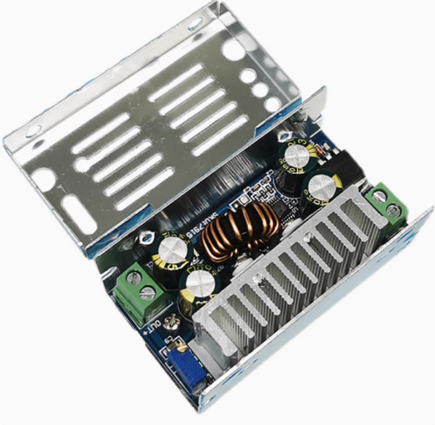
The 200W 15A DC-DC Buck Converter Module is a high-performance, adjustable step-down (buck) voltage regulator engineered for demanding power conversion applications. Based on synchronous rectification technology, this module efficiently converts a higher DC input voltage (8V-60V) into a lower, user-adjustable output voltage (1V-36V) with a continuous current capacity of up to 15A .
Synchronous buck converters replace the traditional catch diode with a low-resistance MOSFET, dramatically improving conversion efficiency (up to 94%) and reducing heat generation compared to asynchronous designs . This makes the module ideal for high-power applications where thermal management is critical.
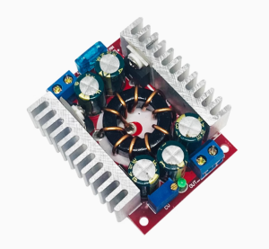
The module features a robust aluminum housing that serves as an effective heatsink, allowing for natural cooling up to 100W and forced-air cooling up to 200W . An onboard multi-turn potentiometer enables stepless output voltage adjustment, while comprehensive protection circuits safeguard against overcurrent and reverse polarity .
Key Features
-
High-Power Output: Delivers up to 200W of output power (with enhanced cooling) and 15A peak output current, suitable for powering high-demand loads .
-
Wide Input & Output Ranges: Accepts DC input from 8V to 60V and provides continuously adjustable output from 1V to 36V (default factory setting 12V) .
-
Synchronous Rectification Technology: Uses synchronous MOSFET switching instead of a Schottky diode, achieving up to 94% conversion efficiency and significantly reducing heat generation .
-
Compact Aluminum Housing: The module is encased in a durable aluminum shell (70x38x31mm) that acts as a built-in heatsink for effective thermal management .
-
Dual Cooling Capacity: Under natural convection (passive cooling), the module supports 100W continuous output. With added forced-air cooling, it can sustain up to 200W .
-
Adjustable Output via Potentiometer: An onboard multi-turn potentiometer allows for stepless output voltage adjustment from 1V to 36V, with a default factory setting of 12V .
-
Built-in Protection Features: Includes overcurrent protection (OCP) and reverse polarity protection to prevent damage during fault conditions .
-
Non-isolated Step-Down Topology: The module is a non-isolated BUCK converter, meaning the input and output share a common ground, which simplifies integration but requires proper grounding practices .
-
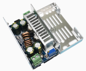
High-Current Screw Terminals: Features solderless, high-current screw terminals for secure, tool-free wiring of input (IN+, IN-) and output (OUT+, OUT-) connections .
Technical Specifications
Pinout & Connection Guide
The module features clearly labeled screw terminals for simple, secure wiring. No soldering is required for the main power connections .
Input Terminals (Power Source)
Output Terminals (Load Connection)
Voltage Adjustment
Important Wiring Notes:
-
IN+ = Input Positive: Connect to the positive terminal of your battery or DC power supply .
-
IN- = Input Negative: Connect to the negative terminal (ground) .
-
OUT+ = Output Positive: Connect to the positive terminal of your load (e.g., LED, motor, battery) .
-
OUT- = Output Negative: Connect to the negative terminal of your load .
⚠️ Critical Safety Warning: While the module has reverse polarity protection (reverse connection will not burn the module ), it is best practice to always double-check your wiring before applying power. The module does NOT have short circuit protection at the output in the traditional sense; it relies on overcurrent protection to limit current .
Usage Guide
Important Preliminary Steps
⚠️ Use a Multimeter: The factory default output is often set to 12V . However, it is recommended to always measure the output with a multimeter before connecting your load and adjust the potentiometer to the exact voltage required by your device.
Wiring Instructions
-
Set Initial Voltage: Before applying power, turn the potentiometer counter-clockwise about 10-15 turns to set it to the minimum voltage.
-
Connect Input: Connect your DC power source (8-60V) to the IN+ and IN- terminals. Ensure correct polarity. The module has reverse polarity protection, but it is still best practice to double-check .
-
Adjust Output Voltage: Place a multimeter on the output terminals. Apply input power. Slowly turn the potentiometer clockwise while watching the multimeter until you reach your desired output voltage.
-
Connect Load: Turn off input power, connect your load to the OUT+ and OUT- terminals, and then re-apply power.
Thermal Management & Power Derating
The maximum output power depends entirely on the cooling solution you provide:
Tip: For continuous operation above 100W, forced-air cooling is strongly recommended to prevent overheating and ensure reliable operation.
Typical Applications
Q: What is the advantage of "synchronous rectification" on this 200W buck converter?
Synchronous rectification replaces the traditional Schottky diode (used in “asynchronous” converters) with a low-resistance MOSFET. This reduces conduction losses and voltage drop across the switching element, resulting in higher efficiency (up to 94%) and significantly less heat generation at high output currents (10A-15A) .
Q: What is the maximum current I can draw from this module?
The module is rated for a normal output current of 10A continuous and a peak of 15A . However, achieving 15A requires excellent cooling (forced air) and a low voltage differential. For long-term reliability, it’s recommended to stay within the 10A range unless actively cooled .
Q: Does this module have Constant Current (CC) mode for charging batteries?
This module is primarily a Constant Voltage (CV) regulator. It has built-in Overcurrent Protection (OCP) that limits the maximum current to approximately 15A for protection purposes . However, it does not offer a user-adjustable constant current (CC) mode. For lithium battery charging, you need a dedicated CC/CV charger.
Q: How much cooling does this module need to run at 200W?
At 200W, the module will generate substantial heat. Natural cooling is only sufficient for up to 100W . To achieve 150W-200W, you must use active cooling, such as a 12V fan blowing directly across the aluminum heatsink housing .
Q: Can I increase the output voltage above 36V?
The specified maximum output voltage is 36V . Exceeding this may damage the module or cause instability. While the chip might theoretically go higher, the module components are selected for a safe 1-36V range.
Q: Why does the output current drop when I increase the output voltage?
This is a matter of power conservation (Input Power = Output Power / Efficiency). The module has a maximum power output (200W). If you increase the output voltage, the maximum available output current will decrease proportionally (Power = Voltage × Current). For example, at 24V, the maximum current is 200W / 24V = 8.3A.
Q: What is the difference between "Natural Cooling" (100W) and "Enhanced Cooling" (200W)?
“Natural Cooling” is passive cooling relying on the aluminum housing alone, sufficient for 100W. “Enhanced Cooling” requires an external 12V fan blowing air over the housing to carry away the extra heat, allowing the module to handle 200W without overheating .
Q: Does the module have short circuit and reverse polarity protection?
The module has Reverse Polarity Protection (connecting the input backward will not burn the module) . It also has Overcurrent Protection (OCP) that limits the current to about 15A, effectively acting as short circuit protection .
Q: What is the voltage tolerance of the output?
The output is adjustable and stable within the 1-36V range. However, like all switch-mode power supplies, there will be a small amount of output ripple (typically < 50mV). For sensitive analog circuits, adding an additional filter capacitor on the output may be beneficial.
Q: Is the output isolated from the input?
No. This is a non-isolated BUCK converter . The input ground (IN-) and output ground (OUT-) are common. Do not use this module for applications requiring galvanic isolation between the source and the load.