

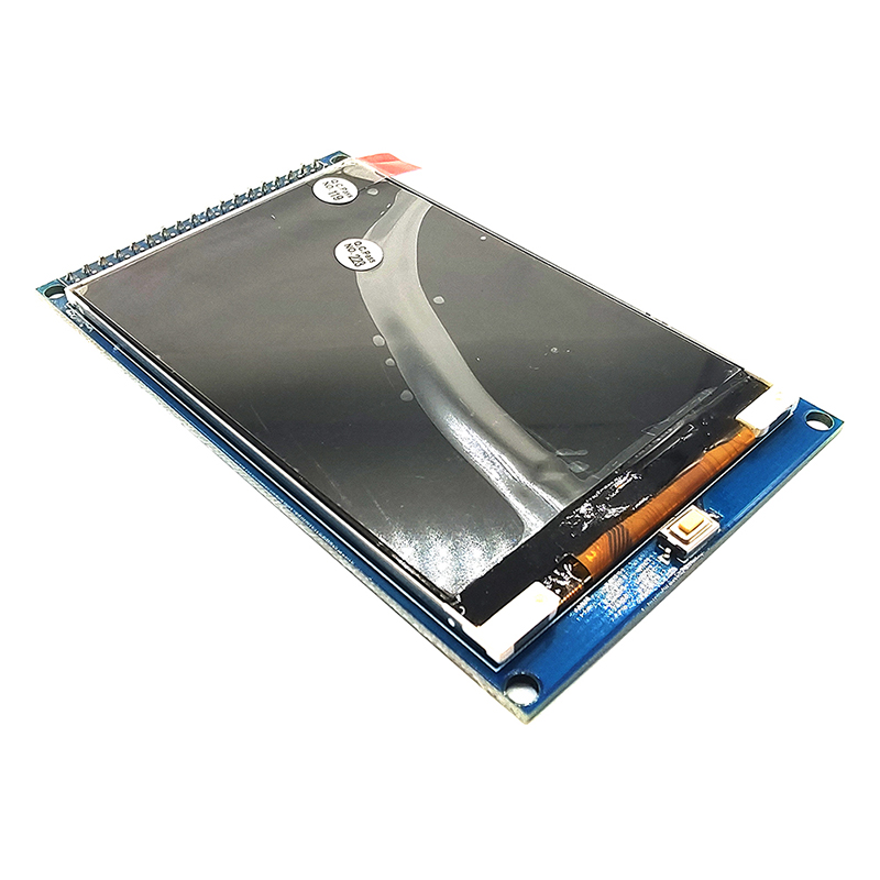
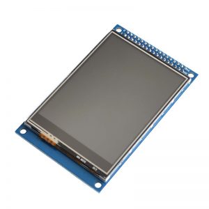
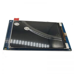
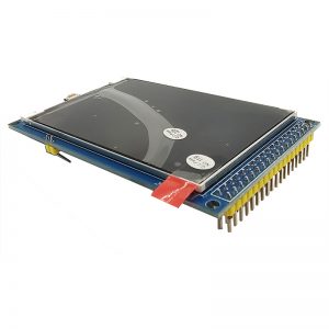


Product Description
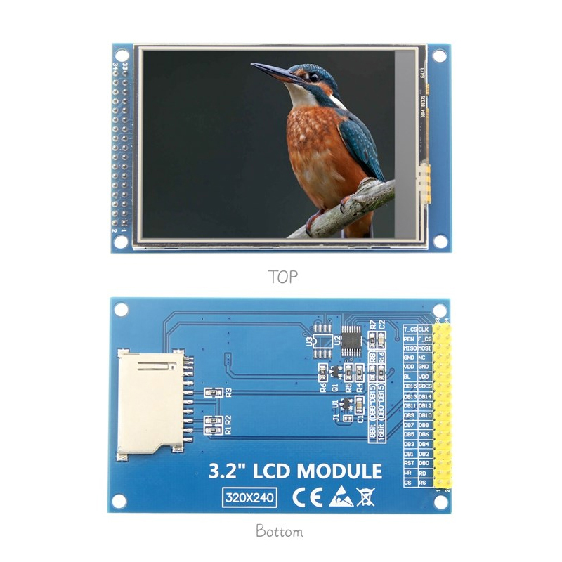
3.2-inch color screen, support 16BIT RGB 65K color display, display rich colors
240×320 resolution for clear display
Support 8-bit/16-bit parallel bus switching (the default is 16-bit), fast transfer speed
Supports ALIENTEK STM32 Mini, Elite, WarShip, Explorer, and Apollo development boards for direct plug-in use
Support for touch function
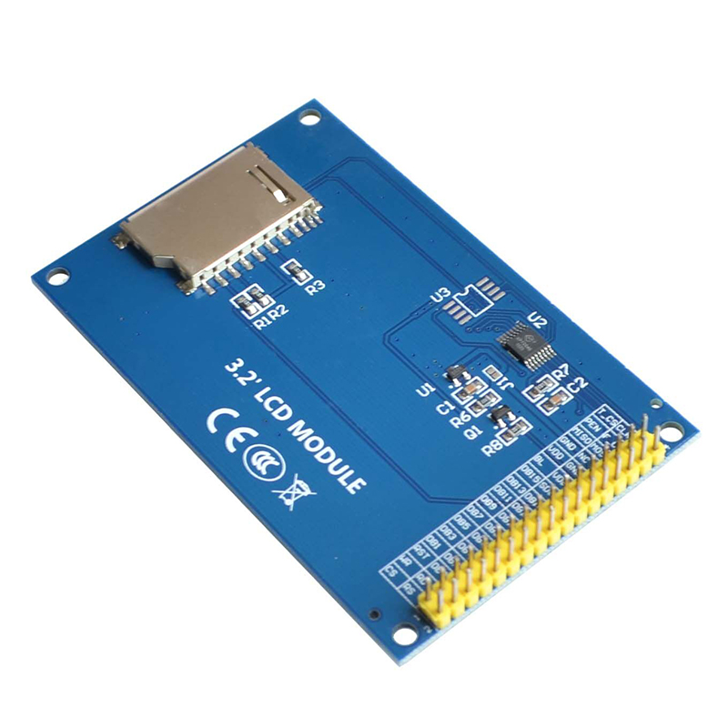
Support SD card function expansion
Provides a rich sample program for STM32 and C51 platforms
Military-grade process standards, long-term stable work
Provide underlying driver technical support
Product Parameters
Display Color: 16BIT RGB 65K color
Screen Size: 3.2(inch)
Screen Type: TFT
Driver: IC ILI9341
Resolution: 320*240 (Pixel)
Module Interface: 8Bit or 16Bit parallel interface
Active Area: 48.6×64.8 (mm)
Touch Screen Type: resistive touch screen
Touch: IC XPT2046
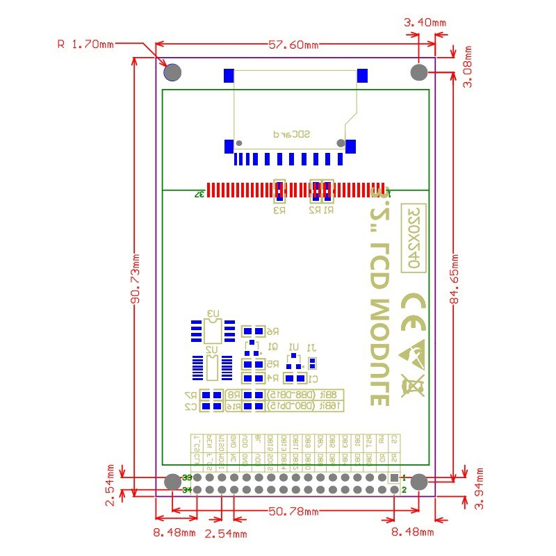
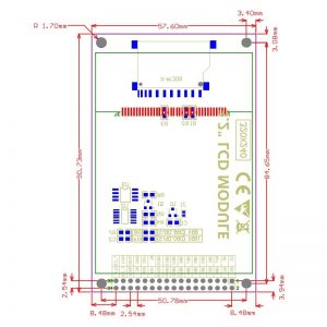
Module PCB Size: 57.60×90.73 (mm)
Operating Temperature: -20℃~60℃
Storage Temperature: -30℃~70℃
Operating Voltage: 3.3V/5V
Power Consumption: TBD
Rough Weight(Package containing): 55 (g)
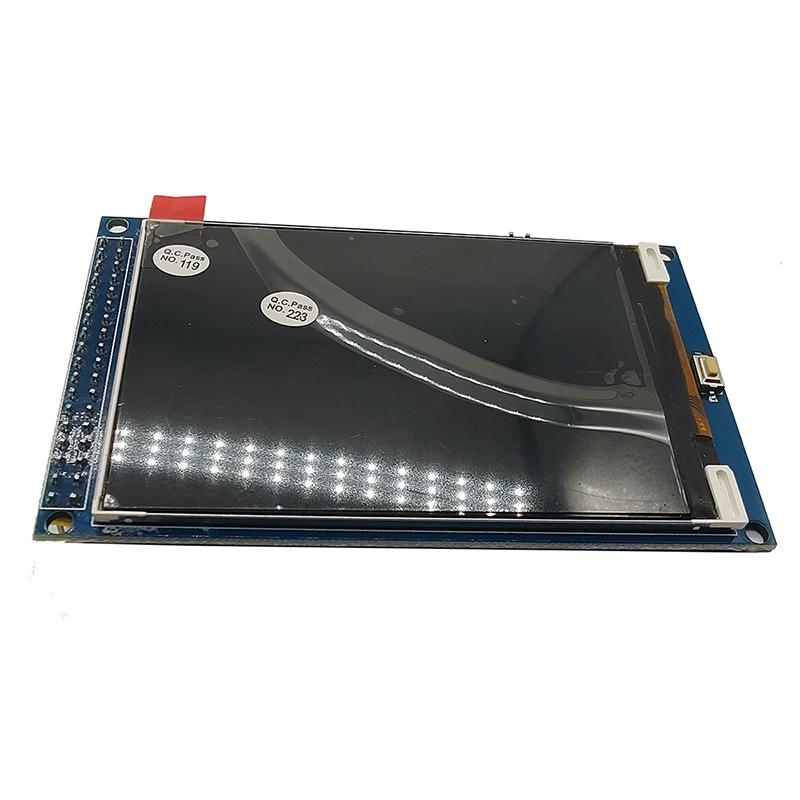
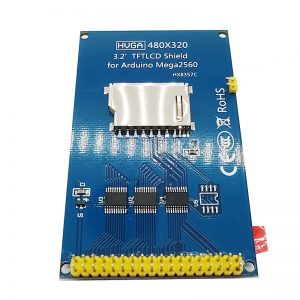
The red box in the above figure is the 8-bit/16-bit data bus mode switch, which is described as follows:
Solder R16 with 0Ω resistor or short circuit directly, and disconnect R8: select 16-bit data bus mode (default), use DB0~DB15 data pin
Solder R8 with 0Ω resistor or short circuit directly, and disconnect R16: select 8-bit data bus mode, use DB8~DB15 data pin
Number Pin Label Description
1 CS LCD reset control pin( low level enable)
2 RS LCD register / data selection control pin(high level: register, low level: data)
3 WR LCD write control pin
4 RD LCD read control pin
5 RST LCD reset control pin( low level reset)
6 DB0 LCD data bus low 8-bit pin(When 8-bit parallel data bus mode is selected, the lower 8-bit data pins are not used)
7 DB1
8 DB2
9 DB3
10 DB4
11 DB5
12 DB6
13 DB7
14 DB8 LCD data bus high 8-bit pin
15 DB9
16 DB10
17 DB11
18 DB12
19 DB13
20 DB14
21 DB15
22 SDCS SD card selection control pin (used when using the SD card expansion function, this test program is not used)
23 BL LCD backlight control pin(High level light)
24 VDD Module power positive pin (module has integrated voltage regulator IC, so the power supply can be connected to 5V or 3.3V)
25 VDD
26 GND Module power ground pin
27 GND
28 NC Undefined, reserved
29 MISO Touch screen SPI bus data input pin
30 MOSI Touch screen SPI bus data output pin
31 PEN Touch screen interrupt detection pin(Low level when a touch occurs)
32 F_CS Flash chip select control pin (used when using the Flash extension function, this test program is not used)
33 T_CS Touch screen IC chip select control pin(Low level enable)
34 CLK Touch screen SPI bus clock control pin