Product Overview
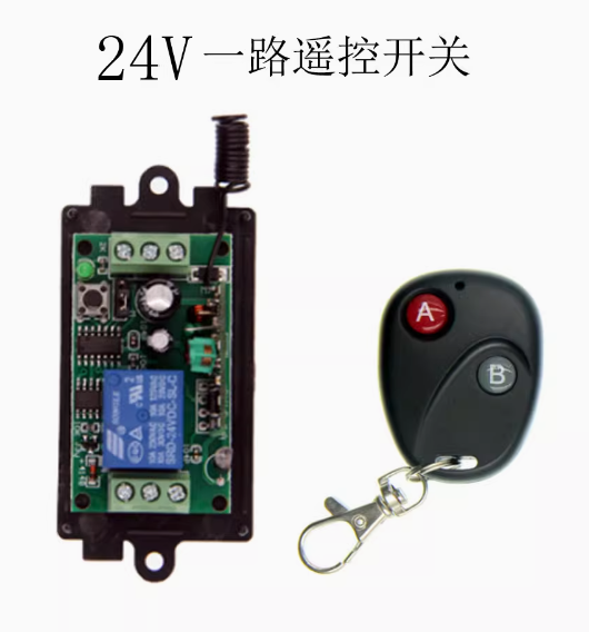
The 24V Single-Channel Wireless Receiver Board is a professional-grade wireless control solution designed for seamless integration into 12V and 24V DC systems. This module serves as a bridge between a wireless remote and a DC-powered device, allowing you to control motors, pumps, LED lighting, access control systems, and other 24V equipment without complex wiring or programming .
The system includes a compact receiver board designed for DC 12V or 24V operation , paired with a 2-button A/B remote controller. The 433MHz wireless frequency ensures stable signal penetration through walls and obstacles, providing reliable control for industrial equipment, automation projects, and automotive applications .
Whether you are retrofitting existing machinery, building automated gates or barriers, or developing custom control systems, this module offers a simple, effective solution.
Key Features
-
DC 12V/24V Power Compatibility: The receiver is designed to operate on 12V or 24V DC power , making it ideal for automotive, industrial control, and battery-powered applications.
-
2A Relay Output: Features a built-in relay capable of switching loads up to 2A at 24V DC , suitable for controlling motors, solenoid valves, LED lighting, and other DC-powered equipment.
-
433MHz Wireless Technology: Operates on the 433.92MHz frequency band, offering better penetration through walls compared to 2.4GHz alternatives, with typical indoor range of 30–40 meters and up to 100 meters in open space .
-
Learning Code Technology: Utilizes EV1527 learning code technology , allowing secure pairing of multiple remotes without specialized programming tools. The receiver can store up to approximately 15 transmitters .
-
Multiple Control Modes: Supports multiple programmable operating modes including Momentary (Jog), Toggle (Self-Lock), and Latched modes, configurable via DIP switches or learning procedure .
-
A/B Remote Controller: The included 2-button remote allows control of a single receiver with two separate functions, or can be programmed to control two different receivers independently .
-
Compact Form Factor: Miniature PCB design (approximately 31mm × 15mm × 4mm) allows for easy integration into control cabinets, junction boxes, or custom enclosures.
-
Status Indicator: An onboard LED provides clear visual feedback for power status, relay activation, and learning mode confirmation .
Technical Specifications
Pinout & Interface Guide
The receiver board is clearly labeled for easy wiring:
Power Input Terminals
Load Output Terminals
-
NO (Normally Open): Connect to the positive wire of your load (device). The relay connects this terminal to COM when activated .
-
COM (Common): Connect to the positive terminal of your DC power supply .
-
NC (Normally Closed): Connects to COM when relay is inactive; typically not used for standard control applications.
Important Wiring Note: The relay only switches the positive supply line. The negative wire of your load must be connected directly to the power supply ground .
Control Interface
-
Learn Button: Used to pair new remote controllers or clear existing codes .
-
Mode Selection (DIP Switch/Jumper): Configures the relay operation mode.
-
Status LED: Indicates power, relay state, and programming status .
Control Modes Explained
The receiver supports multiple operating modes, typically configurable via DIP switches or learning procedure :
Note: Factory default setting is typically Momentary mode . Check your specific module’s labeling for exact DIP switch configuration.
Usage Guide
Wiring Instructions
IMPORTANT: Always disconnect power before wiring.
-
Power Off: Ensure the DC power supply is disconnected.
-
Connect Power: Connect the positive wire from your 12V or 24V DC power supply to the VCC terminal, and the negative wire to the GND terminal .
-
Connect Load:
-
Connect the positive wire of your load (motor, light, solenoid) to the COM terminal .
-
Connect the negative wire of your load directly to the power supply ground .
-
Connect the NO terminal to the load’s positive input (for normally open operation) .
-
Check Connections: Double-check all connections are secure before applying power.
-
Power On: Apply power to the system. The status LED should illuminate, indicating the receiver is ready.
Pairing the Remote (Learning Mode)
The receiver uses learning code technology to pair with remotes :
-
Enter Learning Mode: Press and hold the learning button on the receiver for about 3–5 seconds until the status LED starts blinking slowly .
-
Transmit Signal: Press the button on the A/B remote controller while the LED is blinking.
-
Confirmation: The LED will flash 2–5 times to confirm successful learning, then either stay on or turn off .
Note: The receiver can typically store multiple remote codes (up to 15) . Different buttons on the same remote can be programmed for different functions depending on the receiver’s mode configuration.
Programming the A/B Remote for Dual Control
If your receiver supports two-channel functionality or you have two separate receivers:
Selecting Control Mode
Configure the operating mode using the DIP switches or jumpers on the receiver board :
Clearing All Learned Codes
To reset the receiver and clear all previously paired remotes :
-
Press and hold the learning button for 6–10 seconds until the status LED turns off.
-
Release the button. All codes are now cleared.
Range Testing
To verify sufficient signal strength at your installation location :
-
Position the remote at the intended operating distance.
-
Press the remote button and observe if the receiver responds reliably.
-
If response is intermittent, consider relocating the receiver or using a remote with a higher-gain antenna.
Q: What voltage does this receiver require?
The receiver accepts DC 12V or 24V power input . Do not apply AC mains voltage directly to the receiver—this will damage the unit. For AC applications, use a 12V/24V AC-DC power adapter.
Q: What is the maximum load this relay can handle?
The relay is rated for 2A at 24V DC and can also switch 2A at 120V AC . For inductive loads like motors, it is recommended to derate to 1A–1.5A to account for startup surges.
Q: Can I use this with a 24V motor or pump?
Yes. The receiver’s 2A relay can control motors and pumps within the 2A current rating. For larger motors, use the receiver to control a higher-current contactor or relay instead of switching the motor directly.
Q: What is the effective range of the remote?
In open outdoor space, the range can reach up to 100 meters . Indoors, through walls and floors, the effective range is typically 30–50 meters, depending on building materials . Concrete and metal structures significantly reduce range.
Q: Can I use multiple remotes to control the same receiver?
Yes. The receiver can learn codes from up to approximately 15 different remotes , allowing multiple users to control the same device.
Q: Can a single remote control multiple receivers?
Yes. A single A/B remote can be programmed to control multiple receivers. Different buttons can be assigned to different receivers, or the same button can be learned by multiple receivers
Q: The remote stopped working after I changed the battery. What should I do?
The battery removal may reset the remote’s code transmission. You need to re-pair the remote with the receiver by entering learning mode again
Q: The receiver clicks but my device doesn't turn on. What's wrong?
This indicates the relay is activating but the load circuit is not complete. Check:
-
The load’s negative wire is connected directly to power supply ground .
-
The load’s positive wire is connected to the COM terminal .
-
The NO terminal is connected to the load’s positive input .
-
The load itself is functional.
Q: How do I set the receiver to Momentary (hold to operate) mode?x
Adjust the DIP switches or jumpers on the receiver board according to the label. If using learning-based mode selection, press and hold the learn button multiple times to cycle through modes
Q: The remote works sometimes but not consistently. What could be wrong?
This is often a signal or power issue. Check:
-
Battery strength in the remote (replace with new batteries)
-
Interference from other 433MHz devices nearby
-
Metal obstructions or distance between remote and receiver
-
Power supply stability (ensure voltage does not drop below 10V during operation)
Q: Can I use this receiver with a 433MHz remote from another manufacturer?
Possibly, but not guaranteed. This receiver uses EV1527 learning code technology . If your other remote also uses EV1527 encoding, it may be compatible. Remotes using rolling code (Hopping Code) or other fixed code formats (PT2262) may not be compatible
Q: Can I install this receiver outdoors?
The standard receiver board is not weatherproof. For outdoor installations, mount the receiver inside a weatherproof enclosure rated IP65 or higher
Q: Does the receiver get hot during operation?
The receiver may become slightly warm during normal operation, especially under loads near 2A. Ensure it is installed in a well-ventilated area away from flammable materials.
Q: What wire gauge should I use for power connections?
For 12V/24V 2A applications, use 22–26 AWG wire . For longer wire runs, use thicker wire to minimize voltage drop.
Q: Can I use this to control a 12V solenoid valve or lock?
Yes. The 2A relay is suitable for most 12V solenoid valves and electric locks. Ensure the lock’s current draw does not exceed 2A.
Q: What can I build with this 24V wireless receiver?
Popular applications include:
-
Remote control of 12V/24V motors and actuators
-
Wireless lighting control for 12V/24V LED strips
-
Remote pump control for irrigation or aquariums
-
Access control systems (gates, doors, barriers)
-
Automotive accessories (winches, lighting)
-
Industrial equipment remote control
Q: Can I use this to replace a broken garage door remote receiver?
Yes, provided your garage door opener operates on 12V or 24V DC and the motor current does not exceed 2A. For higher-current openers, use the receiver to control a higher-rated relay or contactor.
Q: Is this system compatible with home automation hubs like Home Assistant?
This is a standalone RF remote system without built-in Wi-Fi. However, you can integrate it with home automation systems using a universal 433MHz RF bridge or software-defined radio (SDR) to capture and retransmit the remote codes.