Product Overview
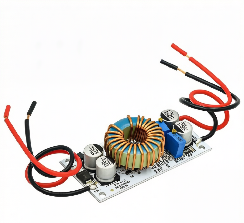
The 250W DC-DC Boost Converter Module is a high-performance step-up power supply designed for demanding applications requiring efficient voltage elevation. Engineered with Constant Voltage (CV) and Constant Current (CC) control, this module provides precise power management for battery charging, LED driving, and industrial equipment.
This non-isolated boost converter accepts a wide DC input range of 12V to 60V and delivers an adjustable output of 12V to 90V with up to 250W of power. Whether you need to boost a 12V car battery to charge a 48V LiFePO4 bank, power high-voltage LED arrays, or create a variable bench power supply, this module delivers exceptional efficiency—up to 96%—while maintaining stable operation under heavy loads .
The module features independent CV (voltage) and CC (current) adjustment via multi-turn potentiometers, making it ideal for lithium battery charging and current-sensitive applications. An integrated heatsink provides passive cooling, and the input reverse polarity protection prevents damage from accidental miswiring .
Key Features
-
250W High Power Output: Capable of delivering up to 250W of output power, suitable for boosting 12V/24V/36V systems to 48V/60V/72V/84V for various industrial loads .
-
Adjustable CV/CC Control: Independent multi-turn potentiometers allow precise setting of output voltage (12-90V) and constant current limit (0.2-8A), essential for battery charging and LED driving .
-
Wide Input/Output Voltage Range: Accepts DC input from 12V to 60V, with output adjustable from 12V to 90V. Note that output voltage must be higher than input voltage .
-
High Conversion Efficiency: Achieves up to 96% efficiency (150kHz switching frequency), minimizing power loss and heat generation .
-
Input Reverse Polarity Protection: Built-in protection prevents damage if input wires are accidentally reversed—a critical safety feature .
-
Overcurrent Protection: Automatically reduces output voltage when input current exceeds 13A, protecting both module and connected devices .
-
Industrial Temperature Range: Rated for operation from -40°C to +85°C, suitable for demanding environments .
-
Compact Design: Compact aluminum housing, with mounting holes for secure installation, weighing approximately 50-65g .
Technical Specifications
Pinout & Connection Guide
The module uses clearly labeled screw terminals for input and output connections.
Input Terminals (Power Source)
Output Terminals (Load Connection)
Adjustment Controls
⚠️ Critical Note: The output voltage must always be higher than the input voltage. This is a boost converter only—it cannot step down voltage .
Usage Guide
Important First-Time Setup
⚠️ Use a Multimeter: The factory default output is often set to a random voltage (approximately 20-50V). Always measure the output with a multimeter before connecting your load and adjust the CV potentiometer to the exact voltage required .
Wiring Instructions
-
Set Initial Outputs: Before powering on, turn the CV potentiometer counter-clockwise about 10-15 turns to set minimum voltage. Turn the CC potentiometer clockwise about 30 turns to set minimum current .
-
Connect Input: Connect your DC power source (12V-60V) to the IN+ and IN- terminals. Ensure correct polarity.
-
Set Output Voltage (CV Mode): Place a multimeter on the output terminals. Apply input power. Slowly turn the CV potentiometer clockwise until you reach your desired output voltage.
-
Set Current Limit (CC Mode) – For LED/Battery Applications:
-
Method: Connect your actual load (LED array or discharged battery)
-
Slowly turn the CC potentiometer clockwise while monitoring the ammeter
-
Stop when you reach the desired current
-
Do NOT short the output to set current – boost converters cannot adjust current in a short-circuit condition
-
Connect Permanent Load: Turn off input power, connect your permanent load, and re-apply power.
Thermal Management & Power Derating
The maximum output power depends on the input voltage differential and cooling provided:
Tip: If the module temperature exceeds 60°C, active cooling (fan) or load reduction is strongly recommended .
Output Power Calculation
The maximum output power is limited by: Output Power = Input Voltage × Input Current × Efficiency
Typical Applications
Q: What is the difference between Constant Voltage (CV) and Constant Current (CC) mode?
CV mode regulates the output voltage at the set level, allowing the load to draw as much current as needed (up to the limit). CC mode regulates the output current at the set level, reducing voltage as necessary to maintain that current limit. CC mode is essential for LED driving (prevents thermal runaway) and lithium battery charging (prevents overcurrent) .
Q: Why can't I set the current limit by shorting the output?
In a boost converter topology, shorting the output prevents the circuit from establishing the necessary voltage differential to regulate correctly. You must connect a real load (like a partially discharged battery or an LED array) when setting the constant current limit for it to work properly
Q: Does this module have reverse polarity protection?
Yes, this module includes input reverse polarity protection to prevent damage if you accidentally connect the input power source backward . However, it is still best practice to double-check your wiring before applying power.
Q: How much cooling does this module need to run at 250W?
At 250W output, the module generates significant heat. Natural cooling is only sufficient for lower power levels. To achieve full 250W power, you need active cooling (a fan) directed at the aluminum heatsink, particularly when operating at higher currents (>8A) .
Q: What is the maximum output current I can draw?
The module is rated for 10A peak input current. The actual output current depends on your input/output voltage differential. For example:
-
12V input to 24V output → approx. 6A output
-
24V input to 48V output → approx. 5A output
-
36V input to 50V output → approx. 4.5A output
Derating applies: higher voltage differential = lower maximum output current .
Q: Can I use this module to charge a lithium battery?Z
Yes, with correct settings. This module supports CC/CV charging:
-
Set the output voltage to the battery’s float voltage (e.g., 4.2V × number of cells in series)
-
Set the CC limit to the desired charge current (e.g., 0.5C of battery capacity)
-
Use a discharged battery when setting the CC limit, as a charged battery will draw less current
Q: Why does my output voltage drop when I connect a load?
This typically happens for one of three reasons:
-
The module is in CC mode: The load is trying to draw more than the set current limit
-
Input power drop: Your input source or wires cannot supply the required current—use thicker wires
-
Overcurrent protection triggered: Input current exceeded 13A, causing voltage reduction
Q: What is the quiescent (no-load) current consumption?
The module draws approximately 10mA when powered with no load (measured at 12V input boosting to 20V). This is normal for a switching regulator and will increase slightly with higher output voltage settings .
Q: Is the output isolated from the input?
No. This is a non-isolated BOOST converter . The input ground (IN-) and output ground (OUT-) are common. Do not use this module for applications requiring galvanic isolation between the source and the load.
Q: Can I connect two of these modules in parallel for more power?
Yes, but with caution. For applications requiring more than 10A output, you can connect two modules in parallel. Adjust each module’s current limit to share the load equally (e.g., set each for 5A if a total of 10A is needed). Ensure the input power supply can handle the combined current draw .