Product Overview
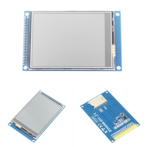
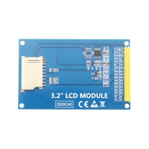
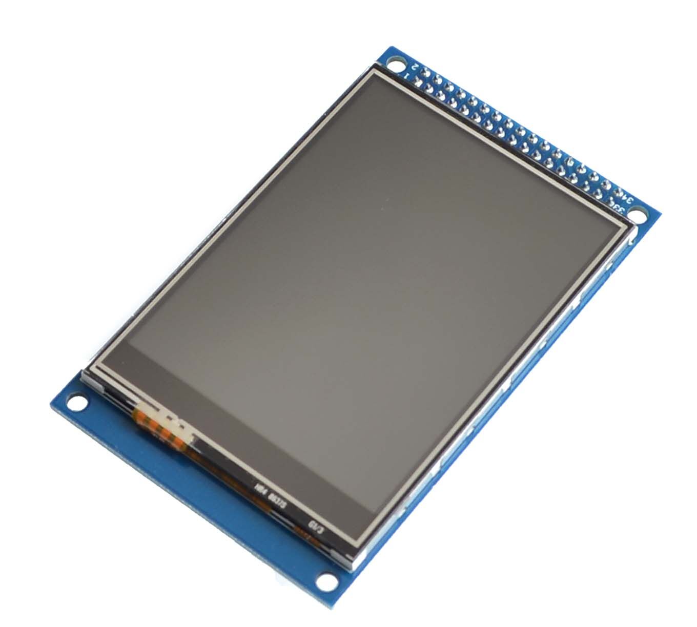
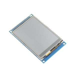
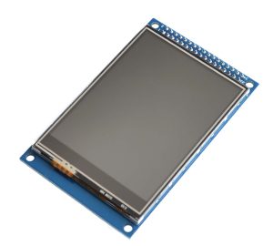
The 3.2 Inch TFT LCD Color Screen Module is a high-resolution 240×320 pixel display featuring the powerful ILI9341 driver IC. This 34-pin module is designed for compatibility with “atomic” 34P LCD interfaces, making it a popular choice for STM32 development boards like the STM32F103 and compatible MCU systems .
This module combines a vibrant 262K-color TFT display with a resistive touchscreen (XPT2046 controller) and an onboard MicroSD card slot – all in one compact 34-pin breakout. Whether you’re building a handheld device, a data logger, or a user interface for an embedded system, this screen provides the pixel control and touch interactivity needed for modern IoT and HMI (Human-Machine Interface) projects.
Supporting both 8-bit and 16-bit parallel interfaces, it offers high-speed data transfer, allowing for smooth UI animations and real-time data visualization. The onboard low-dropout voltage regulator makes it compatible with both 3.3V and 5V logic, so it can safely interface with Arduino, ESP32, STM32, and Raspberry Pi Pico .
Key Features
-
High-Resolution 240×320 Display: QVGA resolution provides crisp text and detailed graphics .
-
26K/65K True Color: Powered by the ILI9341 controller, supporting vibrant color depths .
-
Resistive Touchscreen: Integrated XPT2046 controller (SPI interface) allows for menu selection and GUI interaction .
-
Dual Voltage Compatibility: Onboard regulator supports 3.3V and 5V logic levels, safe for both 5V Arduinos and 3.3V ESP32/STM32 .
-
High-Speed Interface: Supports 8-bit and 16-bit parallel (8080) bus for fast screen updates .
-
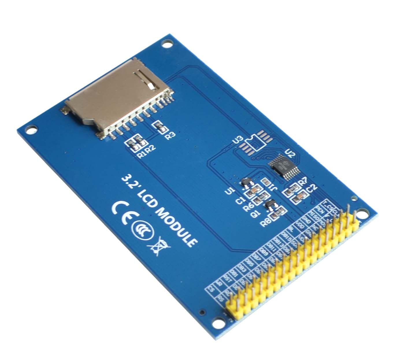
Onboard MicroSD Card Slot: Convenient storage for images, fonts, and data logging .
-
“Atomic” 34P Interface: Standardized pinout compatible with many STM32 development boards and shields .
-
PWM Backlight Control: Dedicated pin allows hardware dimming via an Arduino/ESP32 PWM output .
-
Low Power Consumption: Suitable for battery-powered projects when backlight is managed correctly.
Technical Specifications
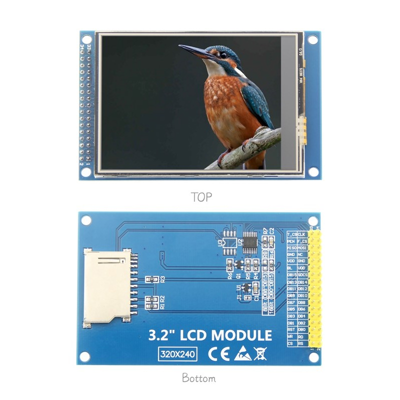
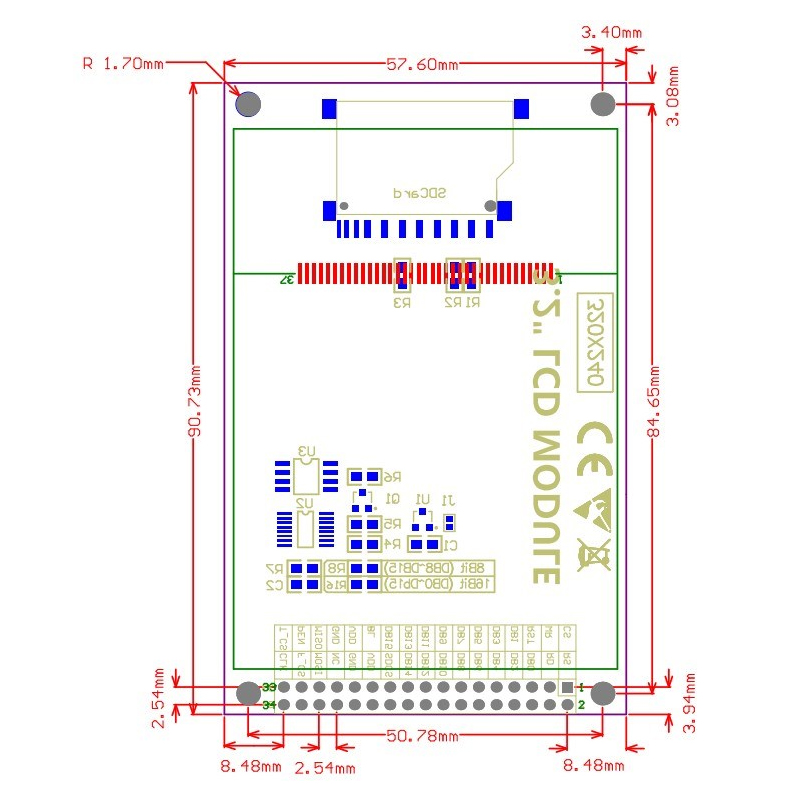
Pinout & Interface Guide
These 34-pin modules follow a relatively standardized pinout specific to the “atomic” 34P interface.
Power & Backlight
-
1 (5V): 5V input (use with 3.3V regulator on board)
-
2 (GND): Power Ground
-
25 (BLVCC): Backlight Power (5V or 3.3V)
-
26 (BLGND): Backlight Ground
-
27 (BLCNT): Backlight Brightness Control (PWM Input)
LCD Control (Direct Connect to MCU)
-
19 (CS): LCD Chip Select (Active Low)
-
20 (RS/DC): Data/Command Select pin
-
21 (WR): Write strobe signal
-
22 (RD): Read strobe signal
-
23 (RESET): LCD Hardware Reset
Data Bus
MicroSD Card (SPI Interface)
-
29 (TP_CS / SD_CS): Card Select (Check your board: sometimes shared with Touch or separate)
-
30 (SCK): SPI Clock
-
31 (MOSI): Master Out Slave In
-
32 (MISO): Master In Slave Out
Touchscreen (XPT2046 – SPI Interface)
-
28 (TP_IRQ): Touch Interrupt (detects screen press)
-
29 (TP_CS): Touch Chip Select
-
30 (TP_SCK): SPI Clock (Shared with SD Card)
-
31 (TP_SI): SPI MOSI (Shared with SD Card)
-
32 (TP_SO): SPI MISO (Shared with SD Card)
-
34 (GND): Ground
Note: Pins may vary slightly between manufacturers. Always verify the silkscreen on your specific board.
Usage Guide
1. Hardware Setup
This module uses a 16-bit parallel interface for the display, which requires more GPIO pins than SPI, but offers significantly faster refresh rates.
-
Connect Power: Connect the 5V and GND pins to your MCU’s 5V and GND.
-
Connect Data Pins: Connect the 16 data pins (DB0-DB15) to available digital I/O pins on your MCU.
-
Connect Control Pins: Connect CS, RS, WR, RD, and RST to additional digital pins.
-
Touch/SD Card: Connect the SPI pins (SCK, MOSI, MISO) to your primary hardware SPI bus. Use unique Chip Select (CS) pins for the Touch and SD Card.
2. Software Setup (STM32 / Arduino IDE)
The ILI9341 is supported by several powerful open-source libraries.
Using the MCUfriend Library (Highly Recommended)
The “MCUfriend” library (often UTFT or UTFTGHL) is specifically designed for these high-pin count TFTs.
-
Download and install the UTFT (or UTFTGHL) library in your Arduino IDE.
-
Look for the hardware profile for “CTE32” or “ITDB32S” (CTE32 is the standard identifier for the 3.2-inch 16-bit module).
-
Pin Assignment: The constructor usually follows the order: (RS, WR, CS, RST, [Optional]).
#include <UTFT.h>
UTFT myGLCD(CTE32, 19, 21, 20, 22);
Using LVGL (High Performance)
For complex user interfaces, LVGL (Light and Versatile Graphics Library) supports the ILI9341 via its MIPI driver interface. You’ll need to implement the send_cmd and send_color callbacks for your hardware .
3. Calibrating Touch (XPT2046)
The resistive touch panel requires calibration:
-
Install the XPT2046_Touchscreen library.
-
Run the calibration sketch provided by the library.
-
The sketch will ask you to touch the corners of the screen.
-
Note the raw ADC (Analog-to-Digital Converter) values and use them in your main project to map the touch coordinates to the 240×320 screen resolution.
4. Troubleshooting SPI Conflicts (Touch + SD Card)
A common issue occurs when the SD card and Touch controller share the same SPI bus but their libraries are not properly managed. If one works and the other doesn’t, specifically check that you are using Hardware SPI for both and that you are correctly setting the Chip Select (CS) pins high/low when switching between the two devices .
Q: What is the difference between the ILI9341 and the ST7789?
The ILI9341 typically runs via a parallel bus (8/16-bit), offering very high speed at the cost of more GPIO pins. The ST7789 usually runs via SPI, which saves pins but is generally slower.
Q: Can I use this screen with an ESP32?
Yes. The ESP32 works great with this screen. The 3.3V logic level is a direct match, and you can use the VSPI or HSPI buses for the Touch and SD Card interfaces .
Q: Is this screen compatible with the Raspberry Pi?
While it is possible, it is complex. The 3.2″ 34-pin module requires 5V logic and a parallel interface; a Raspberry Pi uses 3.3V and typically uses SPI for displays. You would need a level shifter and heavy driver configuration.
Q: What is the optimal voltage to run this display at?
For STM32 and ESP32 (3.3V logic), connect the 3.3V pin directly. For Arduino Uno (5V logic), connect the 5V pin. The on-board regulator handles the conversion .
Q: Why is my SD card not working with the touch screen?
This is usually a Chip Select (CS) conflict. Ensure that the SD Card CS pin and Touch CS pin are connected to different GPIOs. Also, ensure you are de-asserting (setting HIGH) the CS of the SD Card before trying to read data from the Touch controller .
Q: The touch screen is completely unresponsive. What do I do?
1. Check the wiring of TP_IRQ and TP_CS.
2. Run a Touch Calibration sketch. If you get raw readings of zero, the hardware connection or the XPT2046 library configuration is faulty.
Q: What can I build with this 3.2 inch TFT module?
This module is ideal for:
-
Data Loggers: Visualizing sensor data (temperature, humidity) graphically.
-
Smart Home Panels: A central touch interface for controlling lights and switches.
-
Handheld Games: Port classic games like Snake or Tetris.
-
Diagnostic Tools: Car OBD2 dashboards or oscilloscope displays.
-
CNC/3D Printer Controllers: A full-color, touch-based interface (like a RepRapDiscount Smart Controller alternative).