Product Overview
The 3.7V 1A Ultra-Slim Compact Li-ion Battery Charger Module is a complete, highly efficient charging solution designed specifically for single-cell 3.7V lithium-ion and lithium-polymer (LiPo) batteries. This ultra-compact module combines a reliable TP4056 charging IC with DW01 battery protection circuitry—offering both charging management and essential battery safety features in an extremely slim form factor.
Based on the industry-standard TP4056 linear charging IC from Top Power ASIC, this module implements a proper Constant Current/Constant Voltage (CC/CV) charging algorithm that is essential for lithium battery safety and longevity. It charges 3.7V nominal batteries to the correct full charge voltage of 4.2V with an accuracy of ±1.5%.
What sets this module apart is its integrated DW01A battery protection IC and FS8205A dual MOSFETs, which provide comprehensive protection against overcharge, over-discharge, overcurrent, and short circuits. The “with protection” version is ideal for standalone 18650 cells and other batteries that lack their own built-in protection circuit.
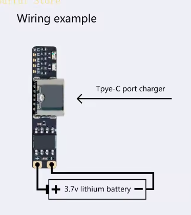
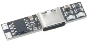
The modern USB Type-C input allows convenient charging via standard USB chargers, power banks, or computer USB ports, while alternative solder pads (IN+/IN-) provide DIY wiring flexibility. The ultra-slim PCB size makes it perfect for portable electronics, DIY power banks, Arduino/ESP32 battery-powered projects, and replacing dead charger circuits in consumer devices.
Key Features
-
Integrated Protection Circuit: Includes DW01A battery protection IC and FS8205A dual MOSFETs, providing overcharge protection (4.28V cutoff), over-discharge protection (3.0V cutoff), overcurrent protection (3A), and short-circuit protection
-
USB Type-C Input: Modern reversible connector for easy connection to standard USB chargers, power banks, or computer USB ports
-
1A Maximum Charge Current: Default charging current of 1000mA (1A), adjustable by changing the programming resistor for lower current applications
-
CC/CV Charging Algorithm: Proper Constant Current / Constant Voltage charging method essential for lithium battery safety and longevity
-
Ultra-Slim Compact Design: Extremely low-profile PCB (approx. 3-4mm thickness) allows for integration into tight spaces and slim portable devices
-
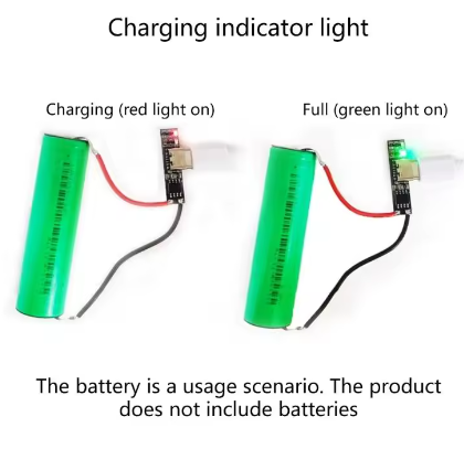
Dual-Color Status Indicator: Red LED indicates charging in progress; Green/Blue LED indicates fully charged or no battery connected
-
Alternative Power Input Pads: IN+ and IN- solder pads allow custom 5V wiring for DIY projects when Type-C is not available
-
Thermal Regulation: Automatically reduces charge current if internal die temperature exceeds safe limits, protecting the chip during high-current charging
Technical Specifications
Pinout & Interface Guide
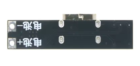
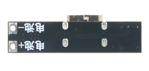
The TP4056 board is clearly labeled with connection points:
Input Side (Power Source)
Battery Connection (Charging Output)
Load Connection (Protected Output)
Status LEDs
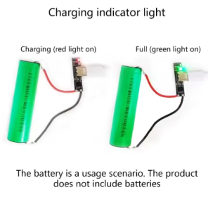
*Note: When no battery is connected, the green LED may be on and the red LED may flash at 1-4Hz intervals.*
Usage Guide
Basic Wiring Instructions
IMPORTANT: This module has NO reverse polarity protection. Connecting the battery backward will damage the chip. Always double-check polarity before connecting.
-
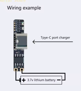
Set Up Power Input: Plug a standard USB Type-C cable into the board’s USB port and connect to a 5V USB charger (capable of at least 1A output). Alternatively, connect a 5V DC supply to the IN+ and IN- pads.
-
Connect Battery: Solder the positive terminal of your 3.7V Li-ion or LiPo battery to the B+ pad. Connect the negative terminal to the B- pad.
-
Connect Load (Optional): For devices requiring protection from battery over-discharge, connect your load to the OUT+ and OUT- terminals. The protection circuit will cut off output if the battery voltage drops below approximately 3.0V.
-
Observe LEDs: When charging begins, the red LED (CHRG) will turn on. When the battery reaches 4.2V and charging completes, the green LED (STDBY) will turn on, and the red LED will turn off.
Setting the Charge Current
The default charge current is 1A (1000mA) set by a 1.2kΩ RPROG resistor on the board. This can be adjusted for smaller batteries:
Current Recommendation: Never charge your battery at a rate greater than 1C (battery capacity). For a 1000mAh battery, a charging current of 400mA is sufficient. If you have small batteries (<1000mAh), replace the R3 resistor with a higher resistance value.
Important Usage Notes
-
Charge Time Calculation: For a fully discharged 2000mAh battery, charging at 1A will take approximately 2 to 2.5 hours.
-
Input Source Requirement: For reliable 1A charging, use a USB power supply rated for at least 1A. A weaker supply will reduce the charge current.
-
Disconnect Load When Charging: It is generally recommended to disconnect the load during charging for optimal battery health.
-
Battery Output 0V? If your battery reads 0V at the OUT terminals, the protection circuit has activated due to over-discharge. The battery is not dead—applying a 5V charge (plugging in USB) will reactivate the protection circuit.
-
Parallel Charging: You can connect two lithium battery cells in parallel to form an equivalent single cell battery with twice the capacity, but do not connect more than two cells at a time.
Charging Process (CC/CV Algorithm)
The module follows a proper 3-stage charging process:
Q: What types of batteries can I charge with this module?
This module is designed specifically for single-cell (1S) 3.7V lithium-ion and lithium-polymer (LiPo) batteries. Common form factors include 18650, 14500, 16340, and pouch cells. It does NOT support 3.2V LiFePO4 batteries, multiple cells in series (2S, 3S, etc.), or NiMH/NiCd batteries
Q: What is the difference between the B+/B- terminals and OUT+/OUT- terminals?
The B+ / B- terminals connect directly to the battery. The OUT+ / OUT- terminals pass through the DW01 protection circuit, which disconnects the load if the battery voltage drops too low (over-discharge protection at ~3.0V) or if current exceeds safe limits (~3A). For most applications, connecting your load to OUT+/OUT- is safer.
Q: Can I use this module while it is charging the battery?
Yes, but with caution. You can power your device from the OUT+/OUT- terminals while the battery is charging. However, it is generally recommended to disconnect the load when charging for optimal battery health.
Q: Does this module have reverse polarity protection?
NO. This module does NOT have reverse polarity protection. Connecting the battery backward will damage the TP4056 chip. Always double-check polarity before connecting.
Q: What does the "with protection" feature mean?
This version includes the DW01A battery protection IC and FS8205A dual MOSFETs. The protection circuit provides overcharge protection (prevents charging beyond 4.2V), over-discharge protection (cuts off load at ~3.0V), and overcurrent protection (~3A). This makes it safe for use with batteries that lack their own built-in protection circuit.
Q: Can I charge multiple batteries in parallel with one module?
Yes, but with extreme caution. You can connect two lithium battery cells in parallel to form an equivalent single cell battery with twice the capacity. However, do not connect more than two cells at a time, and ensure all batteries are at the same voltage before connecting (within 0.1V). Connecting batteries with more than 0.2V difference can risk fire and explosions.
Q: How do I change the charging current from 1A to a lower value?
The charge current is set by the resistor RPROG (R3) on the module. Replace this resistor with a higher value to reduce current. Refer to the resistor table in the “Setting the Charge Current” section.
Q: Can I use a 12V power supply as input?
No. The maximum input voltage is 5.5V DC. Applying 12V will damage the TP4056 chip. Use a 5V USB charger.
Q: The module gets very hot during charging. Is this normal?
Some warmth is normal due to the linear charging method—excess voltage (5V input – 4.2V battery) is dissipated as heat. For 1A charging, power dissipation is approximately 0.8W. The TP4056 has built-in thermal regulation that reduces current if the temperature exceeds safe limits.
Q: Why is my battery not reaching 4.2V or charging very slowly?
Check the following:
Input power: Ensure your USB power supply can deliver at least 1A. A weak supply will reduce the charge current.
Battery health: Old or damaged batteries may not reach full voltage.
Connections: Poor solder joints can create resistance, reducing effective charge current.
Q: What happens when both red and green LEDs are on or flashing?
The red and green LEDs should never be on simultaneously during normal operation. If both are on or the red LED flashes, it may indicate:
No battery connected (green on, red flashing 1-4Hz)
Battery connection problem (poor solder joint)
Battery voltage is too low (below 2.9V, module may be in trickle charge mode)
Q: Why does my battery output 0V?
This typically means the protection circuit has activated due to over-discharge. The battery is not dead—the DW01 protection IC has cut off output to prevent damage. Applying a 5V charge (plugging in USB) will reactivate the protection circuit.
Q: What can I build with this TP4056 charging module?
Popular applications include:
18650 battery chargers for DIY power banks
Arduino/ESP32 portable power supplies with battery backup
DIY Bluetooth speakers with rechargeable batteries
Smart home sensors running on battery power
Rechargeable LED flashlights and lanterns
Portable medical devices requiring battery power
Solar-powered charging systems
Q: Is this module suitable for beginners?
Yes. The TP4056 module is widely recommended for beginners due to its simple connections, clear labeling, and built-in protection features. The onboard LEDs make it easy to see charging status at a glance.
Q: Can I use this module to charge a 4000mAh Li-Po battery?
Yes, but adjust your expectations. For a 4000mAh battery, the maximum safe charging current is 1C = 4A. The TP4056 only provides 1A, so charging will be slower (approximately 4+ hours). This is actually better for battery longevity.