Product Overview
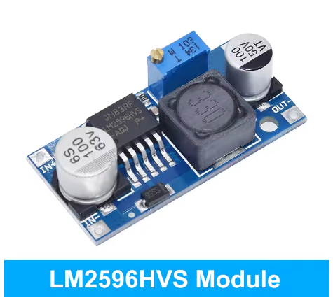
The LM2596HVS Adjustable DC-DC Buck Converter Module is a high-performance, high-voltage step-down switching regulator designed to efficiently convert higher DC voltages (up to 50V) into a lower, continuously adjustable output. Based on the LM2596HVS (High Voltage Series) chip, this module is specifically engineered for applications that require stable power from higher voltage sources such as 36V, 48V, or even 54.6V electric vehicle battery packs .
Unlike standard LM2596 modules that typically max out at 40V input, the LM2596HVS variant supports input voltages up to 50V (absolute maximum 57V), making it the ideal choice for 48V industrial systems, electric vehicles (e-bikes, scooters, golf carts), solar battery banks, and telecom equipment . The module accepts a wide DC input range of 4.5V to 50V and provides an adjustable output from 1.25V to 40V via an onboard precision potentiometer .
At its core, the LM2596HVS utilizes a fixed 150kHz switching frequency and advanced PWM technology to achieve conversion efficiencies of up to 92% . This high efficiency means the module runs cooler and wastes significantly less power than linear regulators, making it ideal for battery-powered or enclosed applications. The module can deliver up to 3A of continuous output current, with higher currents (2.5A-3A) requiring a heatsink for thermal management .
This module is widely used in 48V vehicle accessories (LED lights, fans, USB chargers), industrial control systems, 36V/48V solar charge controllers, and DIY benchtop power supplies. Its ability to step down 48V to 12V, 5V, or any voltage between 1.25V and 40V makes it an incredibly versatile power solution for professionals and hobbyists alike.
Key Features
-
High Input Voltage Range: Accepts DC input from 4.5V to 50V (absolute max 57V), supporting 12V, 24V, 36V, and 48V systems including full 48V e-bike batteries (54.6V max) .
-
Adjustable Output Voltage: Provides continuously adjustable output from 1.25V to 40V via onboard precision potentiometer, allowing you to set exactly the voltage your project needs .
-
High-Efficiency Step-Down Conversion: Achieves up to 92% conversion efficiency, minimizing power loss and heat generation compared to linear regulators .
-
3A High Output Current: Capable of delivering up to 3A of continuous output current. For loads above 2A (or >10W output power), a heatsink is strongly recommended .
-
Fixed 150kHz Switching Frequency: Operates at a fixed 150kHz internal oscillator, allowing for smaller-sized filter components and lower output ripple (≤30mV typical) .
-
Comprehensive Protection: Includes thermal shutdown, current limit protection (two-stage frequency reducing current limit for the output switch), and some variants feature input reverse polarity protection .
-
Ultra-Low Quiescent Current: Standby current consumption of only 5mA-10mA (80µA in shutdown mode), making it suitable for always-on applications in electric vehicles .
-
Industrial Temperature Range: Designed to operate reliably from -40°C to +85°C, suitable for demanding industrial and outdoor environments .
-
Compact Form Factor: Small PCB footprint (approx. 43mm × 21mm × 14mm) allows for easy integration into space-constrained projects .
Technical Specifications
Pinout & Interface Guide
The module is clearly labeled for easy wiring. Connection points include:
Input Side (Power Source)
-
IN+ (VIN): Connect to the positive terminal of your DC power source (e.g., 48V battery, 36V power supply). Observe correct polarity—reverse connection may damage the module .
-
IN- (GND): Connect to the negative terminal (ground) of your DC power source.
Output Side (Load Connection)
-
OUT+ (VOUT): Connect to the positive terminal of your device (e.g., 12V LED strip, 5V microcontroller).
-
OUT- (GND): Connect to the negative terminal (ground) of your device.
User Controls
Status Indicators
Usage Guide
Wiring Instructions
IMPORTANT: Always disconnect the input power source before wiring or modifying connections. Double-check polarity before applying power, as reverse polarity may damage the module. Some variants include reverse polarity protection, but not all .
Basic Setup:
-
Connect Input: Connect the positive wire of your DC power source to the IN+ terminal. Connect the negative wire to the IN- terminal.
-
Set Initial Voltage: Before connecting your load, turn the blue potentiometer fully counter-clockwise to set the output voltage to its minimum. The factory default may be set to a higher voltage.
-
Power On & Adjust Voltage: Apply power. Use a multimeter on the output terminals. Slowly turn the potentiometer clockwise until you reach your desired output voltage.
-
Connect Load: Turn off power, connect your device to OUT+ and OUT-, and re-apply power.
Example 1: 48V E-Bike Battery to 12V Accessories
This is the most common application for the LM2596HVS module. Many e-bikes and electric scooters use 48V batteries (fully charged up to 54.6V), while accessories like LED lights, USB chargers, and GPS units require 12V or 5V power .
-
Connect the 48V e-bike battery’s positive terminal to IN+ and negative to IN-
-
Connect a multimeter to OUT+ and OUT- terminals
-
Apply power from the battery and carefully adjust the potentiometer until the multimeter reads exactly 12.0V
-
Connect your 12V accessories (lights, fans, etc.) to the output terminals
Important Note: With a fully charged 48V battery reaching 54.6V, the LM2596HVS can safely handle this input as its absolute maximum rating is 57V . The module’s quiescent current is only about 5mA, which would take over 4 months to drain a 15Ah battery .
Example 2: Powering 5V Devices from 24V/48V Industrial Supply
In industrial automation, 24V or 48V power rails are common, while sensors and microcontrollers often require 5V power.
-
Connect the 24V or 48V power supply’s positive rail to IN+ and negative rail to IN-
-
Connect a multimeter to OUT+ and OUT- terminals
-
Apply power and carefully adjust the potentiometer until the multimeter reads exactly 5.0V
-
Connect your 5V devices (Arduino, ESP8266, sensors) to the output terminals
Example 3: Variable Bench Power Supply from 48V Source
You can create a variable benchtop power supply for testing circuits from a fixed 48V power supply.
-
Use a 48V DC power supply as the input source
-
Mount the LM2596HVS module in a small enclosure with binding posts
-
Add a voltmeter to the output for real-time monitoring
-
You now have a variable 1.25V-40V bench power supply
Important Considerations
-
Step-Down Only: This is a buck (step-down) converter only. The output voltage must always be lower than the input voltage. The input must be at least 1.5V higher than the desired output for stable regulation .
-
Heat Management: For loads above 2A (or output power >10W), a heatsink is strongly recommended. At 3A continuous, the module can get hot—ensure adequate ventilation .
-
Potentiometer Adjustment: The potentiometer has a wide adjustment range. It may require multiple turns before you see a significant change in the output voltage.
-
Output Power Limitation: The maximum output power is typically limited to 15W without a heatsink. For higher power applications, use a heatsink or active cooling .
-
Input Capacitor: For stable operation, especially when using long input wires, it is good practice to have a 100µF electrolytic capacitor near the input terminals.
-
Output Capacitor: The output capacitor is critical for stability. The module includes appropriate capacitors for most applications.
Q: What is the difference between the LM2596HVS and the standard LM2596?
The LM2596HVS is the “High Voltage” version of the standard LM2596. While the standard LM2596 typically supports up to 40V input, the LM2596HVS supports up to 50V-57V input, making it suitable for 48V battery systems (which can reach 54.6V when fully charged) . The HV version is specifically designed for electric vehicles, solar systems, and industrial applications requiring higher input voltages.
Q: Can this module increase voltage (boost)?
No. This is a buck (step-down) converter only. The output voltage must always be lower than the input voltage. The input must be at least 1.5V higher than the desired output for the regulator to function correctly . To increase voltage, you would need a separate boost converter.
Q: What is the maximum input voltage this module can handle?
The LM2596HVS chip has an absolute maximum rating of 57V, but for practical and safe operation, the recommended input voltage range is 4.5V to 50V . A fully charged 48V e-bike battery (54.6V) is within safe limits. Do not exceed 55V-57V to avoid damaging the module.
Q: What is the maximum output current I can draw from this module?
The module is rated for a maximum of 3A. However, for long-term reliability and without additional cooling, it is recommended to stay within 2A – 2.5A. For loads above 2A (or output power >10W), a heatsink is strongly recommended .
Q: Can I use this module to power a 12V device from a 48V e-bike battery?
Yes, absolutely. This is one of the primary applications for the LM2596HVS. The module efficiently steps down 48V (or up to 54.6V fully charged) to a stable 12V output, perfect for powering LED lights, USB chargers, GPS units, and other accessories on e-bikes and electric scooters .
Q: What is the quiescent current (power consumption when idle)?
The module draws approximately 5mA-10mA when powered but with no load connected. In standby mode (using the shutdown pin), it can be as low as 80µA . This low consumption means it can be left connected to a battery for extended periods without significant drain
Q: The module gets hot. Is this normal?
Some heat is normal, especially under high load (close to 3A). If it is too hot to touch, you should:
-
Attach a heatsink to the LM2596HVS IC’s metal tab
-
Reduce the load current
-
Ensure the input voltage is not excessively higher than the output (e.g., 48V to 3.3V generates more heat than 48V to 12V)
-
Ensure adequate airflow around the module
Q: What is the efficiency of this converter?
The conversion efficiency can reach up to 92% under optimal conditions (higher output voltages generally yield higher efficiency). For example, at 12V input, 3V output, and 3A load, the efficiency is approximately 73% . The efficiency is significantly higher than linear regulators, which typically operate at 30-50% efficiency.
Q: What is the minimum voltage difference required between input and output?
The input voltage must be at least 1.5V higher than the desired output voltage for proper regulation. For example, to get 12V output, you need at least 13.5V input .
Q: What is the output voltage accuracy?
The LM2596HVS has a guaranteed ±4% tolerance on output voltage under specified input voltage and output load conditions
Q: What is the typical output ripple?
The output ripple is typically ≤ 30mV, which is suitable for powering most microcontrollers, sensors, and other sensitive electronics .
Q: The module has power but there is no output voltage. What's wrong?
Follow this checklist:
-
Check the potentiometer setting. It may be turned fully counter-clockwise (minimum voltage). Try turning it clockwise while monitoring the output with a multimeter
-
Check that there is no short circuit on the output terminals
-
Verify that your input voltage is at least 1.5V higher than your target output voltage
-
Ensure your load is not drawing more than 3A, triggering the current limit protection
-
Check if the module is in thermal shutdown (let it cool down and retry)
Q: Can I connect the input in reverse?
Not recommended. Reversing the input polarity (connecting IN+ to negative and IN- to positive) may damage the module. Some variants include reverse polarity protection diodes, but not all. Always double-check your wiring before applying power
Q: Can I use this module to charge a 12V lead-acid or lithium battery?
With caution. The module can provide constant voltage (CV) but lacks a dedicated constant current (CC) charging profile. For battery charging, you need a proper CC/CV charger. If you still choose to use this module, set the output voltage to the battery’s float voltage (e.g., 13.8V for 12V lead-acid) and use a current-limiting resistor. For unattended charging, it is safer to use a dedicated battery charger module.
Q: Can I use multiple modules in parallel for more current?
Not recommended. Running switching regulators in parallel without proper current sharing circuitry can cause one module to supply most of the current, leading to overheating and failure. For higher current requirements, use a single higher-rated converter or design proper load-sharing circuits.
Q: The output voltage drops under load. Why?
This can happen if:
-
The load current exceeds 3A (triggering current limit)
-
The input voltage is too low or unstable (drops below the required minimum differential)
-
The module is overheating and entering thermal throttling
-
The output capacitor is insufficient or faulty
-
The load is highly inductive (motor, solenoid) without proper flyback protection
Q: Can I use this module in a 60V system?
No. The LM2596HVS has an absolute maximum rating of 57V. A 60V system (e.g., a fully charged 52V nominal battery can reach 58.8V) exceeds this rating and may damage the module. For 60V+ systems, look for a buck converter with a higher input voltage rating (e.g., LM2597HV or other high-voltage buck converters).