Description
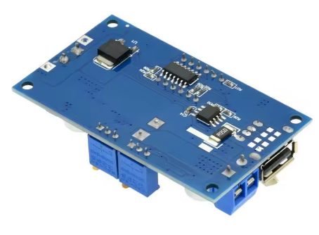
The 5A XL4015 CC-CV Step-Down Power Module is a versatile, high-performance DC-DC buck converter designed for applications requiring precise constant current (CC) and constant voltage (CV) regulation. Whether you need to charge lithium batteries, drive high-power LEDs, or create a benchtop power supply with adjustable current limiting, this module delivers reliable, efficient performance.
At the heart of this module is the XL4015 chip from XLSEMI – a 180KHz to 300KHz fixed frequency PWM buck converter that integrates a high-current 5A power MOSFET . This advanced design achieves conversion efficiencies of up to 96%, significantly outperforming older LM2596-based modules .
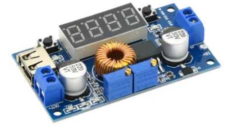
Built-in Dual Display: Unlike standard voltage-only regulators, this module features a built-in dual LED display that shows both output voltage and output current in real-time . The upper display shows voltage, while the lower display shows current, allowing you to monitor your application at a glance without needing an external multimeter.
CC-CV (Constant Current – Constant Voltage) Explained:
This module operates in two distinct modes, automatically switching between them based on load conditions :
Key Applications :
-
Lithium Battery Charger: Set the float voltage (e.g., 4.2V for single Li-Ion cells) and charging current – the module automatically switches from CC to CV when the battery reaches full charge. Dual LED indicators show charging status.
-
LED Constant Current Driver: Drive high-power LEDs at their specified current (e.g., 3A, 5A) without needing additional resistors. The module maintains a constant current regardless of LED forward voltage variations.
-
Adjustable Bench Power Supply: With built-in current limiting and real-time voltage/current display, this module can power sensitive circuits safely – if your prototype shorts, the current limit prevents damage .
Comprehensive Protection Features :
-
Built-in thermal shutdown – automatically shuts down when overheated
-
Current limiting – user-adjustable from 0-5A via onboard potentiometer
-
Output short protection – protects module and load during fault conditions
-
Over-temperature protection – auto-restart when temperature normalizes
Important Operating Note: This module is a step-down (buck) converter only. The input voltage must always be at least 1.5V higher than the desired output voltage. It cannot step up voltage .
Whether you are building a custom battery charger, designing an LED lighting system, or creating a safe benchtop power supply, the XL4015 CC-CV module with voltage and current display provides the precision, power, and visibility you need.
Key Features
-
Dual LED Display – Built-in display shows output voltage (upper) and output current (lower) in real-time; no external multimeter needed for monitoring
-
CC-CV (Constant Current – Constant Voltage) Control – Independently adjustable current limit (0-5A) and output voltage for battery charging and LED driving
-
5A Maximum Output Current – Integrated 5A power MOSFET delivers up to 5A peak (3A-4A recommended continuous with adequate cooling)
-
Wide Input Voltage Range – Accepts DC 5V to 38V input (8V-36V recommended), compatible with 12V, 24V, and 36V power systems
-
Adjustable Output Voltage – Output can be set from 0.8V to 30V via onboard multi-turn potentiometer
-
High Conversion Efficiency – Up to 96% efficiency minimizes power loss and heat generation
-
75W Maximum Output Power – Capable of delivering up to 75W output power (with adequate cooling)
-
Comprehensive Protection – Built-in thermal shutdown, over-current limiting, and output short protection
-
Low Output Ripple – <50mV typical ripple provides clean DC output for sensitive electronics
-
Wide Operating Temperature – -40°C to +85°C for reliable operation in various environments
Technical Parameters
Usage Guide
How CC-CV Works
This module automatically switches between two regulation modes :
-
Constant Current (CC) Mode: When the load tries to draw more current than the user-set limit, the module reduces the output voltage to maintain the current at the set value. The blue CC indicator LED lights up.
-
Constant Voltage (CV) Mode: When the load draws less than the set current limit, the module maintains the output voltage at the user-set value. This is the normal operating mode for most loads.
Example – Charging a 3.7V Li-Ion Battery (2200mAh):
-
Float voltage = 4.2V
-
Charging current = 2200mA (1C)
-
Module starts in CC mode (constant 2200mA, voltage rises as battery charges)
-
When battery reaches 4.2V, module switches to CV mode (constant 4.2V, current gradually decreases)
-
When current drops to 10% of set value, green “full” LED indicates charge complete
Pinout Description
Display Indicators :
-
Upper Display (Red/Green): Shows output voltage
-
Lower Display (Blue/Red): Shows output current
-
Blue LED: Indicates Constant Current (CC) mode active – current limiting engaged
-
Red LED: Indicates charging in progress
-
Green LED: Indicates battery full / CV mode
Wiring Instructions
Step 1 – Connect Input Power
-
Connect the positive (+) wire of your DC power source to IN+
-
Connect the negative (-) wire to IN-
-
Input voltage must be at least 1.5V higher than desired output voltage
Step 2 – Connect Load
-
For battery charging: Connect battery positive to OUT+, negative to OUT-
-
For LED driving: Connect LED anode to OUT+, cathode to OUT-
-
For general use: Connect your load to OUT+ and OUT-
Setting the Output Voltage (No Load)
⚠️ IMPORTANT: Do this with no load connected to the output
-
Power on the module with nothing connected to the output terminals
-
Read the upper display to see the current output voltage
-
Turn the “Voltage” potentiometer (typically the blue trimpot) to adjust:
-
Set to desired voltage (e.g., 4.2V for single Li-Ion, 12.6V for 3S LiPo)
Setting the Output Current Limit
⚠️ CRITICAL: This step must be done with the output shorted
-
Short the output terminals – Connect OUT+ directly to OUT- with a thick wire
-
The display will show the short-circuit current – the lower display will indicate the current limit setting
-
Turn the “Current” potentiometer (the other blue trimpot) to adjust:
-
Set to desired current (e.g., 1A for 1000mAh battery, 3A for 10W LED)
-
Remove the short – the module is now configured
Note: When you short the output, the blue CC indicator LED will light up – this is normal and indicates the module is in constant current mode .
Critical Adjustment Note – Multi-Turn Potentiometers
This is the most important point for new users. The module uses multi-turn potentiometers (typically 25-30 turns from end to end) .
If the output voltage is not changing when you turn the screw:
-
You have likely reached the end of the adjustment range and need to turn in the opposite direction
-
Try turning the screw counter-clockwise many turns (10-15 full rotations) until the voltage starts to decrease
-
If voltage remains at input voltage, the potentiometer is at its maximum – keep turning counter-clockwise
Many modules ship with the voltage preset to approximately 20V – do not be alarmed if your initial reading is high .
Charging Lithium Batteries – Step by Step
-
Determine battery parameters: For a single 18650 (3.7V, 2200mAh):
-
Set voltage (no load): Adjust “Voltage” potentiometer to 4.2V
-
Set current (output shorted): Short output, adjust “Current” potentiometer to 2.2A
-
Remove short and connect battery
-
Monitor charging:
-
Red LED ON = charging (CC mode)
-
Blue LED ON = current limiting active (normal during charging)
-
Green LED ON = full (CV mode, current has dropped to 10% of set value)
Driving High-Power LEDs – Step by Step
-
Determine LED specifications: e.g., 10W LED requires 3.3V @ 3A
-
Set voltage (no load): Adjust “Voltage” potentiometer to 3.3V
-
Set current (output shorted): Short output, adjust “Current” potentiometer to 3A
-
Remove short and connect LED
-
The module will regulate constant current – voltage will adjust automatically to maintain 3A; blue LED indicates active CC mode
Display Calibration
If your display readings differ from a trusted multimeter:
-
Long press the right button for 2 seconds to enter calibration mode (display will flash)
-
Light touch the right button to increase the displayed value by one unit
-
Light touch the left button to decrease the displayed value by one unit
-
Long press the right button for 2 seconds to save and exit calibration mode
Important Operating Restrictions
Voltage Limitation (Critical):
This module is a step-down (buck) converter only. The input voltage must always be at least 1.5V higher than the output voltage. If input drops below output, the module cannot regulate and output will follow input .
Reverse Polarity Warning:
This module does NOT have reverse polarity protection . Double-check connections before applying power. If reverse protection is needed, add a high-current diode in series with the input .
Current Limit Behavior:
When the current limit is active (CC mode), the blue CC indicator LED will light . This is normal during battery charging or when powering loads that exceed your set limit.
Example Applications
Installation Tips
-
Polarity Check: Always double-check input polarity before applying power
-
Initial Setup: Set voltage and current with no load before connecting batteries
-
Heatsink: For loads above 2.5A continuous, attach a heatsink to the XL4015 chip
-
Short Protection: The module includes short protection, but avoid prolonged shorts
-
Keep Wires Short: Long wires add resistance and voltage drop, affecting current limit accuracy
-
Input Voltage: For best efficiency, keep input voltage as close to output voltage as practical (minimum 1.5V headroom)
Q: What does the display show?
The upper display shows the output voltage, and the lower display shows the output current in real-time . The input voltage is not displayed on this module .
Q: What is the difference between this module and a standard voltage regulator?
A standard voltage regulator maintains a fixed voltage regardless of current. This CC-CV module allows you to set both the voltage AND the maximum current. When the load tries to draw more than the set current, the module automatically reduces voltage to keep current at the limit . This is essential for battery charging and LED driving.
Q: Why do I need to short the output to set the current?
Shorting the output forces the module into Constant Current (CC) mode, allowing you to set the current limit accurately. This is the correct procedure for all CC-CV modules
Q: Why is my output voltage not changing when I turn the potentiometer?
The module uses a multi-turn potentiometer (25-30 full turns from end to end) . If you reach the end of its range, turning further has no effect. Try turning the screw counter-clockwise many turns until the voltage starts to decrease. The module may ship with output preset to approximately 20V .
Q: What is the maximum continuous current I can draw?
With proper cooling:
-
Up to 3A: Safe without additional cooling
-
3A – 4A: Requires heatsink and adequate airflow
-
4A – 4.5A: Requires good heatsink and cooling
-
5A: Peak/short duration only (chip’s switch current limit)
Q: Can I use this module to charge any lithium battery?
Yes, for any lithium battery (Li-Ion, LiPo, LiFePO4) within the voltage and current range. You must:
Q: Why is my blue LED lit during battery charging?
This is normal. When charging a deeply discharged battery, the module operates in Constant Current (CC) mode, delivering the set current while the battery voltage rises. The blue LED indicates that current limiting is active . When the battery approaches the float voltage, the module switches to Constant Voltage (CV) mode and the blue LED may turn off.
Q: Can I use this module as a benchtop power supply?
Yes. The adjustable current limit and built-in display make this an excellent benchtop supply for prototyping . Set the voltage to your desired level, then set the current limit to a safe value (e.g., 100mA for sensitive circuits). If you accidentally short your circuit, the module will limit current rather than letting damaging current flow.
Q: Does this module have reverse polarity protection?
No. This module does not have reverse polarity protection . Connecting input backwards will instantly destroy the module. If reverse protection is needed, add a high-current diode in series with the input positive line