Product Description
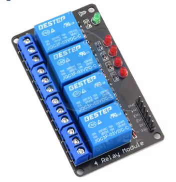
This 5V 4-Way Electromagnetic Relay Module is a practical and reliable switching solution designed for microcontroller-based control systems. It features a straightforward low-level trigger logic, making it intuitively compatible with common development platforms like Arduino, ESP32, and Raspberry Pi. The module operates without optical isolation, providing a direct and cost-effective interface between your digital control signals and high-power AC/DC loads.
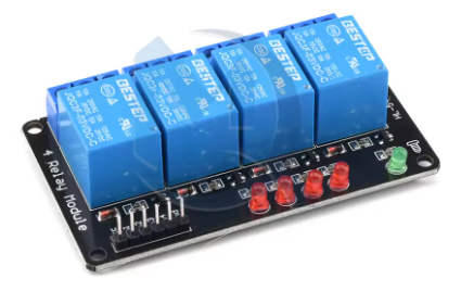
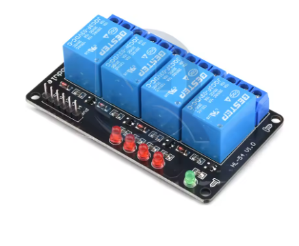
Each of the four channels is equipped with a high-quality electromagnetic relay capable of handling substantial currents. The board includes bright status indicator lights for each relay, providing clear visual feedback of the switching state. Screw terminals ensure secure connections for both the control side and the load side, while the compact form factor makes it easy to integrate into control panels, smart home installations, and automation prototypes. This module is an excellent choice for hobbyists, students, and professionals seeking a simple, effective way to add robust switching capabilities to their projects.
Key Features
-
Low-Level Trigger Logic: The relay activates when the control signal pin is set to LOW (0V/GND), which aligns with the default output behavior of many microcontrollers.
-
Four Independent Channels: Control up to four separate electrical circuits or devices simultaneously from a single control board.
-
Dual-Purpose Relays: Each relay features SPDT (Single Pole Double Throw) contacts, allowing connection to Normally Open (NO) or Normally Closed (NC) terminals for flexible circuit design.
-
Clear Status Indicators: Each channel has a bright LED that illuminates when the relay is energized, providing instant visual confirmation of its state.
-
High-Current Switching: Robust relays are rated to switch loads up to 10A, suitable for a wide range of appliances and equipment.
-
Non-Optocoupler Design: A simplified, direct-drive circuit offers a reliable and economical solution for environments where high-voltage isolation is managed separately.
-
Screw Terminal Blocks: Provide secure and reliable wire connections for both 5V control power and the high-power load circuits.
-
Wide Compatibility: Works seamlessly with 5V logic microcontrollers and development boards using standard male-to-female jumper wires.
Main Parameters
-
Number of Channels: 4
-
Trigger Logic: Low Level (Active LOW)
-
Control Signal Voltage: 5V TTL
-
Module Operating Voltage: 5V DC
-
Relay Contact Rating: 10A @ 250VAC / 10A @ 30VDC
-
Relay Type: Electromagnetic, Single Coil
-
Contact Type: SPDT (COM, NO, NC)
-
Dimensions: Approximately 120mm x 75mm x 18mm
Q: What does "Low-Level Trigger" mean?
It means the relay will turn ON and close its switch contacts when the corresponding control signal pin receives a LOW voltage signal (connected to ground, 0V). The relay turns OFF when the signal pin receives a HIGH voltage signal (5V). This is a common and intuitive mode for many projects.
Q: Why is there no optocoupler, and is that a problem?
This module is designed without optocouplers to reduce cost and complexity, relying on a shared ground between the control circuit and relay coils. It is not a problem if your system uses a single, well-regulated 5V power supply for both the microcontroller and the relay module. Optocouplers are primarily needed for isolation when the control and load circuits use separate or noisy power sources.
Q: Can I control 120V or 240V AC household appliances with this?
Yes, but with critical caution. Each relay is rated for 250VAC, so it can safely switch standard household voltages. You must have appropriate knowledge of working with mains electricity, use proper enclosures, and follow all electrical safety codes. Incorrect wiring can lead to fire, equipment damage, or severe electric shock.
Q: My microcontroller (like Raspberry Pi) uses 3.3V logic. Will this module work?
It may not work reliably. The module is designed for a 5V TTL HIGH signal. A 3.3V signal might be too low to be reliably recognized as a HIGH (OFF) state, potentially causing the relay to remain activated. For 3.3V controllers, a module with optocoupler isolation or a logic level shifter is recommended.
Q: What power supply do I need?
You need a stable 5V DC power supply. The total current required depends on how many relays are ON at once. Each energized relay coil draws about 70-80mA. Therefore, if you plan to have all four ON simultaneously, your 5V supply should provide at least 4 x 80mA = 320mA, plus extra for your microcontroller. A 5V/2A (2000mA) power adapter is a safe and common choice.
Q: Can I use this to control DC loads, like 12V motors?
Yes. The relay contacts are rated for both AC and DC. You can switch DC loads up to 30V at 10A. Connect your DC power source to the COM and NO/NC terminals just as you would for an AC circuit.
Q: The relay clicks but my connected device doesn't turn on. What's wrong?
First, double-check all load-side wiring. Ensure the device is connected between the COM and NO terminals (if you want it ON when the relay is activated). Verify that the device itself works by connecting it directly to its power source. Also, check that the screw terminals are tightened securely on the wires.
Q: Is this product suitable for both individual users and business customers?
Absolutely. For individual makers, students, and hobbyists, it’s a perfect, affordable component for countless projects. For business customers, including startups and OEMs, it serves as a reliable, ready-made solution for integrating switching functions into products or control systems. We support bulk orders and can discuss custom branding or specification adjustments for qualified business inquiries.