8-Pin NRF24L01 Socket Adapter for Wireless Transmitter Module – Plug & Play

SKU: FA2017-0
Input Voltage

4.8V to 12V DC

Output Voltage

3.3V DC (Fixed)

Maximum Output Current

800mA (Well above the peak requirements of the nRF24L01+ PA/LNA versions)

Interface

8-Pin socket for nRF24L01+; 6-Pin header for Microcontroller connection (VCC, GND, CE, CSN, SCK, MO, MI, IRQ)

Dimensions

26mm x 19mm x 12mm

Operating Temperature

-40°C to +85°C

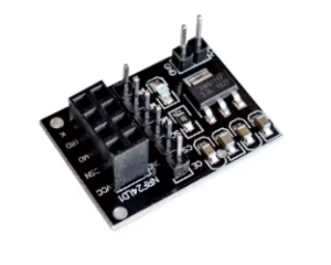
This nRF24L01 8-Pin Socket Adapter is the essential companion for the popular nRF24L01+ wireless transceiver. It is designed to solve the most common challenge engineers and hobbyists face: power instability. Because the nRF24L01 module is highly sensitive to voltage ripples and requires a precise 3.3V supply, drawing power directly from a microcontroller often leads to communication “brown-outs” or failed transmissions.
This breakout board features a dedicated 3.3V voltage regulator and integrated filtering capacitors, providing the “plug and play” reliability needed for both rapid prototyping and long-term industrial monitoring applications.
Key Features
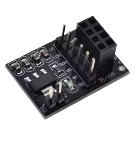
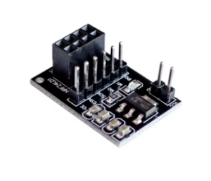
  • Integrated Voltage Regulation: Onboard AMS1117-3.3 chip converts a standard 5V input to a steady 3.3V output.
  • Enhanced Signal Integrity: Built-in bypass capacitors filter out power supply noise, significantly improving wireless range and transmission stability.
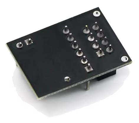
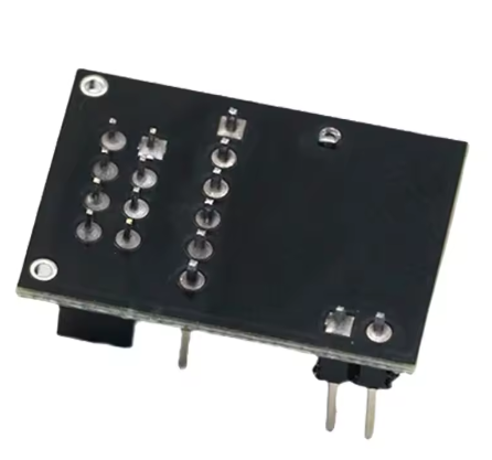
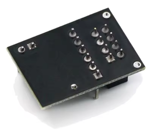
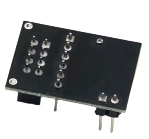
  • Simple Pinout: Breaks out the complex 8-pin header into a single-row header that is breadboard-friendly and easy to label.
  • Power Status LED: A built-in SMD indicator provides immediate visual confirmation that the module is receiving power.
  • Reverse Polarity Protection: Protects your expensive nRF24L01 modules from damage due to incorrect wiring.
Usage Guidelines
  1. Installation: Insert your nRF24L01+ module into the 8-pin female socket on the adapter. Ensure the orientation matches the silkscreen markings.
  2. Power Connection: Connect your power source (typically 5V from an Arduino or external supply) to the VCC and GND pins on the adapter.
  3. Data Connection: Connect the SPI pins (CSN, CE, MOSI, MISO, SCK) directly to your microcontroller’s corresponding SPI pins.
  4. Note: While the adapter accepts 5V for power, ensure your microcontroller’s logic levels are compatible (the nRF24L01+ pins are generally 5V tolerant for data, but always check your specific module datasheet).
Q: Why do I need this adapter if my Arduino already has a 3.3V pin?

The 3.3V pin on many microcontrollers cannot provide enough current during the high-power “burst” phases of wireless transmission. This leads to dropped packets. This adapter uses its own regulator to ensure the radio always has the current it needs.

Q: Can I use this with the "Long Range" (PA/LNA) version of the nRF24L01?

Yes. In fact, it is highly recommended for the high-power versions, as they draw significantly more current than the standard “on-board antenna” versions.

Q: Do I need to solder anything?

Most adapters come with pre-soldered headers and sockets, making them a 100% plug-and-play solution.

Q: Does this adapter convert 5V logic to 3.3V logic for the data pins?

No, this adapter regulates the power supply (VCC). However, the nRF24L01+ data pins are 5V tolerant, meaning you can typically connect them directly to a 5V microcontroller without a logic level shifter.

Q: Is this suitable for bulk industrial integration?

Absolutely. For business customers, these adapters reduce assembly errors and field failures caused by power fluctuations, making them a cost-effective choice for scaled deployments.