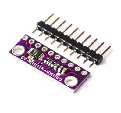
Description
The ADS1115 16-Bit ADC Module is a high-precision, ultra-small, low-power analog-to-digital converter designed for applications requiring accurate analog signal measurement. At its heart lies the genuine Texas Instruments ADS1115 integrated circuit, a 16-bit delta-sigma ADC that delivers exceptional precision for sensor measurement applications where microcontroller built-in ADCs fall short.
Unlike standard microcontroller ADCs that typically offer only 10-bit resolution (1024 steps), the ADS1115 provides true 16-bit resolution (65,536 steps), enabling detection of voltage changes as small as 0.1875mV when using the ±4.096V range. This level of precision is essential for measuring small-signal sensors like load cells, thermocouples, current sensors, and pressure transducers.
The module features a 4-channel input multiplexer (MUX) that can be configured for four single-ended inputs (measuring four separate signals relative to ground) or two differential inputs (measuring the voltage difference between two channels). The onboard Programmable Gain Amplifier (PGA) offers selectable input ranges from ±256mV to ±6.144V, allowing direct measurement of both tiny sensor signals and larger voltages without external signal conditioning.
Communication is handled via the I²C bus with four pin-selectable addresses (0x48, 0x49, 0x4A, 0x4B), allowing up to four modules to be connected on the same bus for a total of 16 analog inputs. The ADS1115 also features an integrated low-drift voltage reference, internal oscillator, and a programmable digital comparator for over/under-voltage detection.
The module operates on a wide supply voltage range of 2.0V to 5.5V and consumes only 150µA in continuous conversion mode, making it ideal for battery-powered IoT devices, portable instrumentation, and remote sensor nodes.
Whether you are building a precision data logger, a battery monitoring system, a weigh scale, or any application requiring accurate analog measurement, the ADS1115 module delivers professional-grade performance in a compact, easy-to-use package.
Key Features
-
True 16-Bit Resolution – 65,536 steps provide exceptional measurement precision for small-signal sensors
-
4-Channel Input Multiplexer – Configurable as four single-ended inputs or two differential inputs
-
Programmable Gain Amplifier (PGA) – Selectable input ranges from ±256mV to ±6.144V for direct measurement of diverse signal levels
-
Ultra-Low Power Consumption – Only 150µA in continuous conversion mode; ideal for battery-powered applications
-
Wide Operating Voltage – 2.0V to 5.5V supply range compatible with 3.3V and 5V systems
-
Programmable Data Rate – 8 SPS to 860 SPS, allowing optimization between speed and noise performance
-
I²C Interface – Simple two-wire communication with four pin-selectable addresses (up to 4 modules on same bus)
-
Internal Low-Drift Voltage Reference – Stable measurements without external reference components
-
Internal Oscillator – No external clock source required for operation
-
Programmable Digital Comparator – Configurable for over-voltage, under-voltage, or window detection with ALERT/RDY output pin
-
Single-Cycle Settling – Each conversion is stable without waiting for filter settling
-
Wide Operating Temperature – -40°C to +125°C, suitable for industrial and automotive applications
Technical Specifications
Q: Why should I use this instead of my microcontroller's built-in ADC?
Most microcontrollers (Arduino Uno, ESP8266, etc.) have 10-bit ADCs (1024 steps), limiting precision. The ADS1115 offers 16-bit resolution (65,536 steps), enabling detection of voltage changes as small as 0.1875mV in the ±4.096V range. Additionally, the ADS1115 provides a programmable gain amplifier, internal voltage reference, and better noise performance than most built-in microcontroller ADCs.
Q: What is the difference between single-ended and differential measurement?
Single-ended measures the voltage on a channel relative to ground (GND). This is suitable for sensors that output a voltage relative to ground. Differential measures the voltage difference between two channels (e.g., A0 and A1), which is ideal for measuring signals with common-mode noise (like thermocouples) or sensors with floating outputs. The ADS1115 supports up to 4 single-ended channels or 2 differential channels.
Q: What is the maximum voltage I can measure with this module?
The maximum input voltage relative to GND is determined by the supply voltage (VDD). With VDD = 5V, the absolute maximum input voltage is VDD + 0.3V (5.3V). However, the PGA’s maximum input range is ±6.144V. For voltages above VDD, external voltage dividers must be used to scale down the input voltage to within the safe range.
Q: How do I change the I²C address?
The ADS1115 has four selectable addresses determined by the ADDR pin connection:
-
ADDR to GND → Address 0x48 (default)
-
ADDR to VDD → Address 0x49
-
ADDR to SDA → Address 0x4A
-
ADDR to SCL → Address 0x4B
This allows up to 4 modules on the same I²C bus (16 total analog inputs).
Q: What are the available PGA gain settings and their uses?
The Programmable Gain Amplifier (PGA) amplifies small input signals before conversion, effectively increasing resolution for small signals. Available ranges are:
-
±0.256V – Maximum resolution for tiny signals (thermocouples, strain gauges)
-
±0.512V, ±1.024V, ±2.048V – Medium-range sensors
-
±4.096V, ±6.144V – Larger signals (battery monitoring, power supplies)
Using the smallest range that accommodates your signal provides the best resolution
Q: What is the maximum sampling rate and how does it affect readings?
The data rate is programmable from 8 to 860 samples per second (SPS). Higher rates (860 SPS) provide faster measurements but higher noise and reduced accuracy for high-frequency signals due to the sinc filter response. Lower rates (8-128 SPS) provide lower noise and better resolution for slowly changing signals. For most sensor applications, 16-128 SPS works well. At 860 SPS, conversion time is approximately 1.3ms per reading.
Q: Can I read all four channels simultaneously?
No. The ADS1115 uses a multiplexer at the front of the ADC, so you can only switch in one channel at a time to make a measurement. To read multiple channels, you must reconfigure the MUX between readings. In single-shot mode, program the configuration register for the desired channel, wait for the conversion to complete (based on data rate), then read the result. Repeat for each channel.
Q: What is the ALERT/RDY pin used for?
The ALERT/RDY pin has two functions:
-
Comparator mode: Asserts when conversion data exceeds programmed high/low thresholds (over/under voltage detection)
-
Conversion ready mode: Asserts when a new conversion is complete, signaling the microcontroller to read the result
This pin can be used to trigger interrupts, reducing the need for continuous polling.
Q: Can I use this module with 3.3V systems like ESP8266 or ESP32?
Yes. The ADS1115 operates at 2.0V to 5.5V, making it compatible with both 3.3V and 5V systems. However, note that the analog input voltage cannot exceed VDD. If powering from 3.3V, inputs are limited to 0-3.3V. The I²C interface works with both voltage levels.
Q: How do I measure voltages higher than 5V?
Use an external voltage divider to scale the voltage down to within the ADS1115’s input range. For example, to measure a 12V car battery with a maximum voltage of 14.4V: Use a divider ratio of approximately 1:4 (e.g., 10kΩ and 2.2kΩ) to scale 14.4V down to ~2.6V. Use precision resistors (0.1% or better) for accuracy. The ADS1115’s 16-bit resolution will preserve measurement precision after scaling.