ADS1115 16-Bit ADC Module – 4-Channel with Programmable Gain Amplifier (PGA) – STEMMA QT / Qwiic Compatible

SKU: FA2176-3
ADC Resolution

16-bit

Input Channels

4 (single-ended) / 2 (differential)

Sampling Rate

8 SPS – 860 SPS (programmable)

PGA Input Ranges

±0.256V, ±0.512V, ±1.024V, ±2.048V, ±4.096V, ±6.144V

Operating Voltage

2.0V – 5.5V DC

Current Consumption

150µA (continuous mode) / Auto shut-down (single-shot mode)

I²C Interface

Up to 400 kHz; four pin-selectable addresses (0x48-0x4B)

Connector Type

STEMMA QT / Qwiic compatible (JST SH) + 0.1" header pins

Description

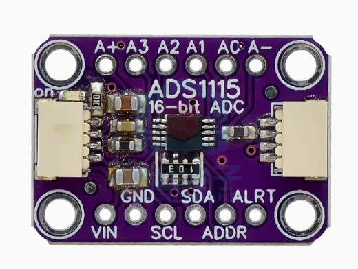
The ADS1115 16-Bit ADC Module is a high-precision analog-to-digital converter breakout board designed for microcontrollers that lack analog inputs or require higher resolution than their built-in ADCs. At its heart lies the Texas Instruments ADS1115 integrated circuit, a 16-bit delta-sigma ADC that delivers exceptional precision for sensor measurement applications .

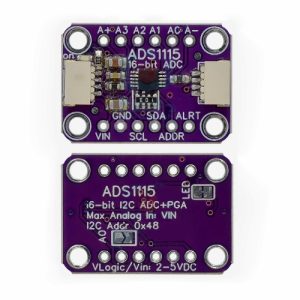
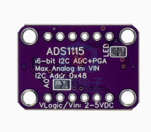
Unlike standard microcontroller ADCs that typically offer only 10-bit resolution (1024 steps), the ADS1115 provides true 16-bit resolution (65,536 steps) , enabling detection of voltage changes as small as 0.1875mV when using the ±4.096V range. This level of precision is essential for measuring small-signal sensors like load cells, thermocouples, current sensors, and pressure transducers .

The module features a 4-channel input multiplexer (MUX) that can be configured for four single-ended inputs (measuring four separate signals relative to ground) or two differential inputs (measuring the voltage difference between two channels). The onboard Programmable Gain Amplifier (PGA) offers selectable input ranges from ±256mV to ±6.144V, allowing direct measurement of both tiny sensor signals and larger voltages without external signal conditioning .

Communication is handled via the I²C bus with four pin-selectable addresses (0x48, 0x49, 0x4A, 0x4B), allowing up to four modules to be connected on the same bus for a total of 16 analog inputs . The module also features an integrated low-drift voltage reference, internal oscillator, and a programmable digital comparator for over/under-voltage detection .

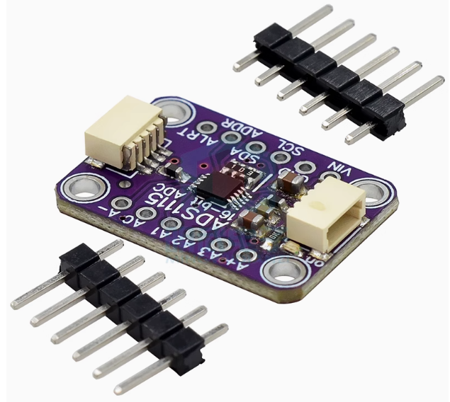
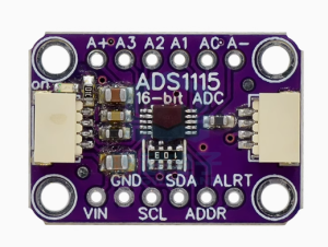
The standout feature of this version is the STEMMA QT / Qwiic compatible connectors on either side of the board. These standardized JST SH connectors allow for solderless plug-and-play connections between your development board and the ADS1115, or to chain it with a wide range of other sensors and accessories using compatible cables . No soldering is required for basic integration.

The module operates on a wide supply voltage range of 2.0V to 5.5V and consumes only 150µA in continuous conversion mode, making it ideal for battery-powered IoT devices, portable instrumentation, and remote sensor nodes .

Whether you are building a precision data logger, a battery monitoring system, a weigh scale, or any application requiring accurate analog measurement, the ADS1115 module delivers professional-grade performance in a compact, easy-to-use package.

Key Features

  • True 16-Bit Resolution – 65,536 steps provide exceptional measurement precision for small-signal sensors 

  • 4-Channel Input Multiplexer – Configurable as four single-ended inputs or two differential inputs 

  • Programmable Gain Amplifier (PGA) – Selectable input ranges from ±256mV to ±6.144V for direct measurement of diverse signal levels; up to x16 gain 

  • STEMMA QT / Qwiic Compatible Connectors – Solderless plug-and-play connections using standard JST SH cables; chain multiple devices on the same bus 

  • Ultra-Low Power Consumption – Only 150µA in continuous conversion mode; single-shot mode with auto shut-down for battery-powered applications 

  • Wide Operating Voltage – 2.0V to 5.5V supply range compatible with 3.3V and 5V systems 

  • Programmable Data Rate – 8 SPS to 860 SPS, allowing optimization between speed and noise performance 

  • Internal Low-Drift Voltage Reference – Stable measurements without external reference components 

  • Internal Oscillator – No external clock source required for operation 

  • Programmable Digital Comparator – Configurable for over-voltage, under-voltage, or window detection 

  • Single-Cycle Settling – Each conversion is stable without waiting for filter settling

  • Ferrite Beads for Noise Reduction – Keeps AVDD and AGND quiet for cleaner measurements 

  • Standard 0.1″ Header Pins Included – For traditional breadboard or perfboard use when solderless connection is not desired 

  • Four Mounting Holes – For easy attachment to enclosures or project boxes 

  • Wide Operating Temperature – -40°C to +125°C, suitable for industrial and automotive applications

Technical Specifications 

Specification Value
ADC Resolution 16-bit 
Input Channels 4 (single-ended) / 2 (differential) 
Sampling Rate 8 SPS – 860 SPS (programmable) 
PGA Input Ranges ±0.256V, ±0.512V, ±1.024V, ±2.048V, ±4.096V, ±6.144V 
Operating Voltage 2.0V – 5.5V DC 
Current Consumption 150µA (continuous mode) / Auto shut-down (single-shot mode) 
I²C Interface Up to 400 kHz; four pin-selectable addresses (0x48-0x4B) 
Connector Type STEMMA QT / Qwiic compatible (JST SH) + 0.1″ header pins 
Board Dimensions 25.4mm × 17.8mm × 4.6mm / 1.0″ × 0.7″ × 0.2″ 
Weight 1.8g / 0.1oz 
Operating Temperature -40°C to +125°C 

Typical Usage

  • Precision Sensor Measurement – Load cells, thermocouples, RTDs, pressure sensors, gas sensors, and humidity sensors 

  • Battery Monitoring Systems – Measure battery voltage, charge/discharge current, and cell balancing in Li-ion/LiFePO4 packs 

  • Portable Instrumentation – Handheld multimeters, data loggers, and field measurement devices 

  • IoT Sensor Nodes – Add high-precision analog measurement to ESP8266/ESP32-based wireless sensors using STEMMA QT cables 

  • Weigh Scales & Force Measurement – Precision weight sensing with strain gauge load cells

  • Current Sensing – Measure shunt voltage for current monitoring in power supplies and motor controls

  • Temperature Measurement Systems – Precision thermocouple and RTD measurements for industrial and laboratory applications 

  • Consumer Electronics – High-precision analog interfaces for consumer devices 

  • Factory Automation and Process Control – Industrial sensor data acquisition and monitoring 

  • Medical Devices – Low-power, high-precision measurements for portable medical instruments

Q: What does STEMMA QT / Qwiic compatible mean?

STEMMA QT and Qwiic are standardized connector systems for I²C devices. They use 4-pin JST SH connectors that allow you to connect the module to compatible development boards or sensors using simple plug-and-play cables, with no soldering required. The connectors on either side also allow you to daisy-chain multiple devices on the same I²C bus .

Q: Why should I use this instead of my microcontroller's built-in ADC?

Most microcontrollers (Arduino Uno, ESP8266, etc.) have 10-bit ADCs (1024 steps), limiting precision. The ADS1115 offers 16-bit resolution (65,536 steps) , enabling detection of voltage changes as small as 0.1875mV in the ±4.096V range. Additionally, the ADS1115 provides a programmable gain amplifier, internal voltage reference, and better noise performance than most built-in microcontroller ADCs .

Q: What is the difference between single-ended and differential measurement?
  • Single-ended measures the voltage on a channel relative to ground (GND). Suitable for sensors that output a voltage relative to ground.

  • Differential measures the voltage difference between two channels (e.g., A0 and A1). Ideal for measuring signals with common-mode noise (like thermocouples) or sensors with floating outputs. The ADS1115 supports up to 4 single-ended channels or 2 differential channels .

Q: How do I change the I²C address?

The ADS1115 has four selectable addresses determined by the ADDR pin connection :

  • ADDR to GND → Address 0x48 (default)

  • ADDR to VDD → Address 0x49

  • ADDR to SDA → Address 0x4A

  • ADDR to SCL → Address 0x4B

This allows up to 4 modules on the same I²C bus (16 total analog inputs).

Q: What is the maximum input voltage I can measure?

The maximum input voltage relative to GND is determined by the supply voltage (VDD). With VDD = 5V, the absolute maximum input voltage is VDD + 0.3V (5.3V). However, the PGA’s maximum input range is ±6.144V. For voltages above VDD, external voltage dividers must be used to scale down the input voltage to within the safe range .

Q: What are the available data rate settings and how do they affect readings?

The data rate is programmable from 8 to 860 samples per second (SPS) :

  • Higher rates (860 SPS) – Faster measurements but higher noise; useful for capturing transient events

  • Lower rates (8-128 SPS) – Lower noise and better resolution for slowly changing signals like temperature
    For most sensor applications, 16-128 SPS works well.

Q: Can I use this module with 3.3V systems like ESP8266, ESP32, or Raspberry Pi?

Yes. The ADS1115 operates at 2.0V to 5.5V, making it compatible with both 3.3V and 5V systems. However, note that the analog input voltage cannot exceed VDD. If powering from 3.3V, inputs are limited to 0-3.3V. The I²C interface works with both voltage levels . Example code is available for Arduino, CircuitPython, and Raspberry Pi .

Q: What is the ALERT pin used for?

The ALERT pin (also called RDY) has two programmable functions :

  • Comparator mode – Asserts when conversion data exceeds programmed high/low thresholds (over/under voltage detection)

  • Conversion ready mode – Asserts when a new conversion is complete, signaling the microcontroller to read the result
    This pin can be used to trigger interrupts, reducing the need for continuous polling.

Q: How do I measure voltages higher than 5V?

Use an external voltage divider to scale the voltage down to within the ADS1115’s input range. For example, to measure a 12V car battery with a maximum voltage of 14.4V: Use a divider ratio of approximately 1:4 (e.g., 10kΩ and 2.2kΩ) to scale 14.4V down to ~2.6V. Use precision resistors (0.1% or better) for accuracy. The ADS1115’s 16-bit resolution will preserve measurement precision after scaling.

Q: What is the difference between the ADS1115 and ADS1015?

The ADS1115 is a 16-bit ADC while the ADS1015 is a 12-bit ADC . Both are from the same family, but the ADS1115 offers higher resolution for precision applications. The ADS1015 has a faster maximum data rate of 3300 SPS, while the ADS1115 reaches 860 SPS . For most sensor applications requiring high accuracy, the ADS1115 is the preferred choice.