Description
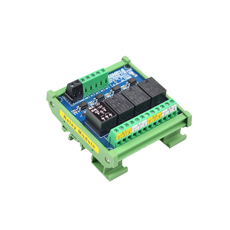
The BMZ-04R1-E is a compact, industrial-grade 4-channel relay output module designed for PLC signal amplification, control system interfacing, and automation projects requiring multiple relay outputs. Building on the success of our 2-channel version, this 4-channel model offers greater I/O density while maintaining the same professional features: a rugged plastic enclosure, standard 35mm DIN-rail mounting, and full optocoupler isolation.
Each of the four channels is equipped with a high-quality Songchuan SPDT relay, capable of switching loads up to 10A at 250V AC or 30V DC — sufficient for most industrial loads including solenoid valves, contactors, motors, lighting, and heating elements. The optocoupler isolation provides complete galvanic separation between the low-voltage control side (your PLC or microcontroller) and the high-voltage load side, protecting sensitive electronics from back EMF, voltage spikes, and ground loop noise.
The BMZ-04R1-E features wide input compatibility (3.3V to 5V) and accepts both NPN (sinking) and PNP (sourcing) control signals automatically. This makes it an ideal signal amplifier for 3.3V microcontrollers (ESP32, Raspberry Pi Pico, STM32), 5V systems (Arduino, 5V PLCs), and mixed-voltage environments.
Typical applications include CNC machine control, industrial automation panels, PLC output expansion, building management systems, and laboratory automation. The enclosed design and DIN-rail mounting make it suitable for professional control cabinet installation.
Features
-
4 independent relay channels with optocoupler isolation
-
High-quality Songchuan brand relays (SPDT changeover contacts)
-
Wide control signal range: 3.3V – 5V DC (NPN and PNP compatible)
-
Industrial plastic enclosure with 35mm DIN-rail mounting
-
Galvanic isolation between control side and load side
-
Screw terminals for all control inputs and load connections
-
LED indicators per channel for relay status
-
Compact 4-channel design for space-saving installation
-
Tool-free DIN-rail clip for easy mounting and removal
-
Rated for up to 10A resistive load per channel
Technical Parameters
Usage Guide
1. Understanding NPN vs. PNP Input Modes
The BMZ-04R1-E automatically accepts both NPN and PNP control signals:
No jumpers or configuration needed — simply connect your control signal.
2. Power Supply Connection
⚠️ The module requires 24V DC for operation. Do not connect 5V or 3.3V to the power terminals. The control signals are 3.3V–5V, but relay coils require 24V.
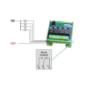
3. Control Signal Wiring (Input Side)
Connect your PLC, microcontroller, or other controller to the input terminals:
4. Load Connection (Output Side)
Each relay channel provides three screw terminals:
Example (AC Fan Control using NO):
AC Live ──→ COM (Channel 1)
Fan Live ──→ NO (Channel 1)
Fan Neutral ──→ AC Neutral (direct)
5. Wiring Examples by Controller Type
Example 1: 5V Microcontroller (Arduino)
Arduino Digital Pin 2 ──→ IN1
Arduino Digital Pin 3 ──→ IN2
Arduino Digital Pin 4 ──→ IN3
Arduino Digital Pin 5 ──→ IN4
Arduino GND ──→ COM (Input)
Module VCC ──→ 24V Power Supply (+)
Module GND ──→ 24V Power Supply (-)
Example 2: 3.3V Microcontroller (ESP32)
ESP32 GPIO 12 ──→ IN1
ESP32 GPIO 13 ──→ IN2
ESP32 GPIO 14 ──→ IN3
ESP32 GPIO 15 ──→ IN4
ESP32 GND ──→ COM (Input)
Module VCC ──→ 24V Power Supply (+)
Module GND ──→ 24V Power Supply (-)
Example 3: NPN PLC Output (Mitsubishi FX Series)
PLC Y0 ──→ IN1
PLC Y1 ──→ IN2
PLC Y2 ──→ IN3
PLC Y3 ──→ IN4
PLC 0V Common ──→ COM (Input)
Module VCC ──→ 24V Power Supply (+)
Module GND ──→ 24V Power Supply (-)
Example 4: PNP PLC Output (Siemens LOGO!)
PLC Q1 ──→ IN1
PLC Q2 ──→ IN2
PLC Q3 ──→ IN3
PLC Q4 ──→ IN4
PLC 0V Common ──→ COM (Input)
Module VCC ──→ 24V Power Supply (+)
Module GND ──→ 24V Power Supply (-)
6. Sample Arduino Code
int relayPins[4] = {2, 3, 4, 5};
void setup() {
for (int i = 0; i < 4; i++) {
pinMode(relayPins[i], OUTPUT);
digitalWrite(relayPins[i], LOW);
}
}
void loop() {
for (int i = 0; i < 4; i++) {
digitalWrite(relayPins[i], HIGH);
delay(1000);
digitalWrite(relayPins[i], LOW);
delay(500);
}
}
7. DIN-Rail Mounting Instructions
The BMZ-04R1-E features a standard 35mm DIN-rail channel:
Mounting:
-
Tilt the module slightly backward (top edge angled away from rail)
-
Hook the top edge onto the top of the DIN rail
-
Rotate the module downward until the bottom spring clip engages with a click
Removal:
-
Use a flathead screwdriver to pull down the release tab at the bottom
-
Tilt the module upward while holding the release tab
-
Lift the module off the rail
8. Important Notes
-
Control signals: 3.3V–5V only — do not apply 24V to IN1–IN4.
-
Module power: 24V DC only — do not connect AC or higher voltage to VCC/GND.
-
The optocoupler provides isolation, but AC load wiring still requires proper safety practices (enclosures, circuit breakers, fusing).
-
For inductive loads (motors, solenoids, contactors), derate to ≤5A and consider adding external snubber protection.
-
Always connect the input COM terminal to your controller’s GND for proper signal reference.
Q: What is the difference between BMZ-02R1-E and BMZ-04R1-E?
The BMZ-04R1-E has 4 channels (compared to 2 channels on the BMZ-02R1-E). The 4-channel version is physically wider (approx. 95mm vs. 50mm) but otherwise shares the same features: optocoupler isolation, 3.3V–5V control, NPN/PNP compatibility, Songchuan relays, and DIN-rail mounting.
Q: What is the control signal voltage range?
The BMZ-04R1-E accepts control signals from 3.3V to 5V DC. This covers:
-
3.3V microcontrollers (ESP32, Raspberry Pi Pico, STM32, Teensy)
-
5V microcontrollers (Arduino Uno/Nano/Mega, PIC, 8051)
-
5V PLC outputs
-
3.3V logic outputs from sensors and industrial controllers
Q: Can I use 24V control signals directly?
No. The input circuit is designed for 3.3V–5V only. Applying 24V to IN1–IN4 will damage the optocoupler inputs. If you need a 24V control version, please see our BMZ-04R1-E 24V input version (separate product).
Q: Why does the module require 24V power when control signals are only 5V?
The 24V supply powers the relay coils and optocoupler output circuits. Relays require significantly more current than a microcontroller can provide, and the 24V supply ensures consistent, reliable switching even when all 4 channels are active simultaneously. This is standard for industrial relay modules.
Q: How much current does the module draw from the 24V supply?
-
Idle (no relays active) : ~25–35mA at 24V
-
One relay active : ~50–60mA at 24V
-
Four relays active : ~170–200mA at 24V
A standard 24V DIN-rail power supply (e.g., 24V / 0.5A or 1A) is more than sufficient.
Q: Can I use this module with a Raspberry Pi (3.3V GPIO)?
Yes. Raspberry Pi GPIO outputs (3.3V) work perfectly. Connect:
-
Raspberry Pi GPIO pin → IN1 (etc.)
-
Raspberry Pi GND → COM (Input)
-
Module VCC → 24V power supply
-
Module GND → 24V power supply GND
The 24V supply GND and Raspberry Pi GND must be connected through the COM terminal (they share a common reference).
Q: Can I use this module with an Arduino (5V logic)?
Yes. Arduino digital outputs (5V) are ideal. Connect directly as shown in the usage guide — no level shifting required.
Q: What brand are the relays? Why is this important?
This module uses Songchuan relays, a leading industrial relay manufacturer. Benefits include:
-
10 million+ mechanical operations lifespan
-
Consistent contact resistance (no intermittent failures)
-
Proven reliability in industrial environments (factories, HVAC, machinery)
-
Low coil power consumption compared to generic relays
Many low-cost modules use unbranded relays with unknown quality. We specify Songchuan to ensure long-term reliability.
Q: Can I mix AC and DC loads on different channels?
Yes. Each of the 4 channels is fully independent. You can control:
As long as each load stays within the relay’s ratings (10A / 250V AC or 30V DC).
Q: Is this module suitable for controlling inductive loads (motors, pumps, contactors)?
Yes, but with precautions. Inductive loads generate back EMF (voltage spikes) when switched off, which can damage relay contacts over time. For best reliability:
-
Derate the current: use ≤5A for motors (instead of 10A rating)
-
Add external snubber protection: RC snubber for AC loads, flyback diode for DC loads
-
Consider our SSR (Solid State Relay) modules for very frequent switching
Q: Can I use this module for business / industrial applications?
Absolutely. The BMZ-04R1-E is designed specifically for professional use, including:
-
CNC machine peripheral control (spindle brake, coolant pump, work light, dust collector)
-
PLC output expansion (adding relay outputs to systems with insufficient capacity)
-
Industrial automation panels (conveyors, packaging machines, assembly stations)
-
Building management systems (HVAC valves, lighting contactors, exhaust fans)
-
Laboratory automation (reaction vessels, pumps, heaters)
-
Control cabinet installations (DIN-rail mounting, enclosed design)
Q: How do I mount the BMZ-04R1-E on a DIN rail?
The module has a standard 35mm top-hat DIN-rail channel on the rear:
-
Hook the top edge of the module onto the DIN rail
-
Rotate the module downward toward the rail
-
Press firmly until the bottom spring clip snaps into place with an audible click
-
To remove, pull down the release tab at the bottom and lift upward
Q: What is the mechanical and electrical life of the relay?
Electrical life depends on load type (resistive lasts longer than inductive) and switching frequency.
Q: Does the module have LED indicators?
Yes. Each of the 4 channels has a dedicated red LED that lights up when the relay is active (NO contact closed to COM). This is useful for troubleshooting and visual confirmation during operation.
Q: What are the physical dimensions?
Approximate dimensions: 95mm (width) × 86mm (height) × 40mm (depth).
This compact 4-channel design allows mounting in crowded control cabinets alongside other DIN-rail components (power supplies, terminal blocks, PLCs).
Q: Does the module have any certifications?
The BMZ-04R1-E is designed for industrial use and complies with relevant safety standards for relay modules. For specific certification details (CE, RoHS, etc.), please refer to the product datasheet or contact our support team.
Q: Can I cascade multiple BMZ modules together?
Yes. You can mount multiple BMZ-02R1-E and BMZ-04R1-E modules side by side on the same DIN rail. Each module requires its own 24V power connection (or can share a common 24V bus if current capacity allows). Control signals come from your PLC or microcontroller independently.
Q: What happens if I connect the control signals before applying 24V power?
The module is designed to handle this safely. The optocoupler inputs are passive and will not be damaged if 24V power is absent. However, the relays will not operate until 24V is applied. For predictable startup behavior, we recommend applying 24V power before or simultaneously with control signals.
Q: Is the BMZ-04R1-E suitable for home automation projects?
Yes, it works well for advanced home automation, especially when you need to control multiple AC loads from a low-voltage controller. However, the 24V power requirement means you’ll need a small 24V power supply. For 5V-only DIY setups, our open-frame 5V relay modules may be more convenient. The BMZ series excels when you want enclosed, DIN-rail mountable modules for a clean, professional installation.