Description
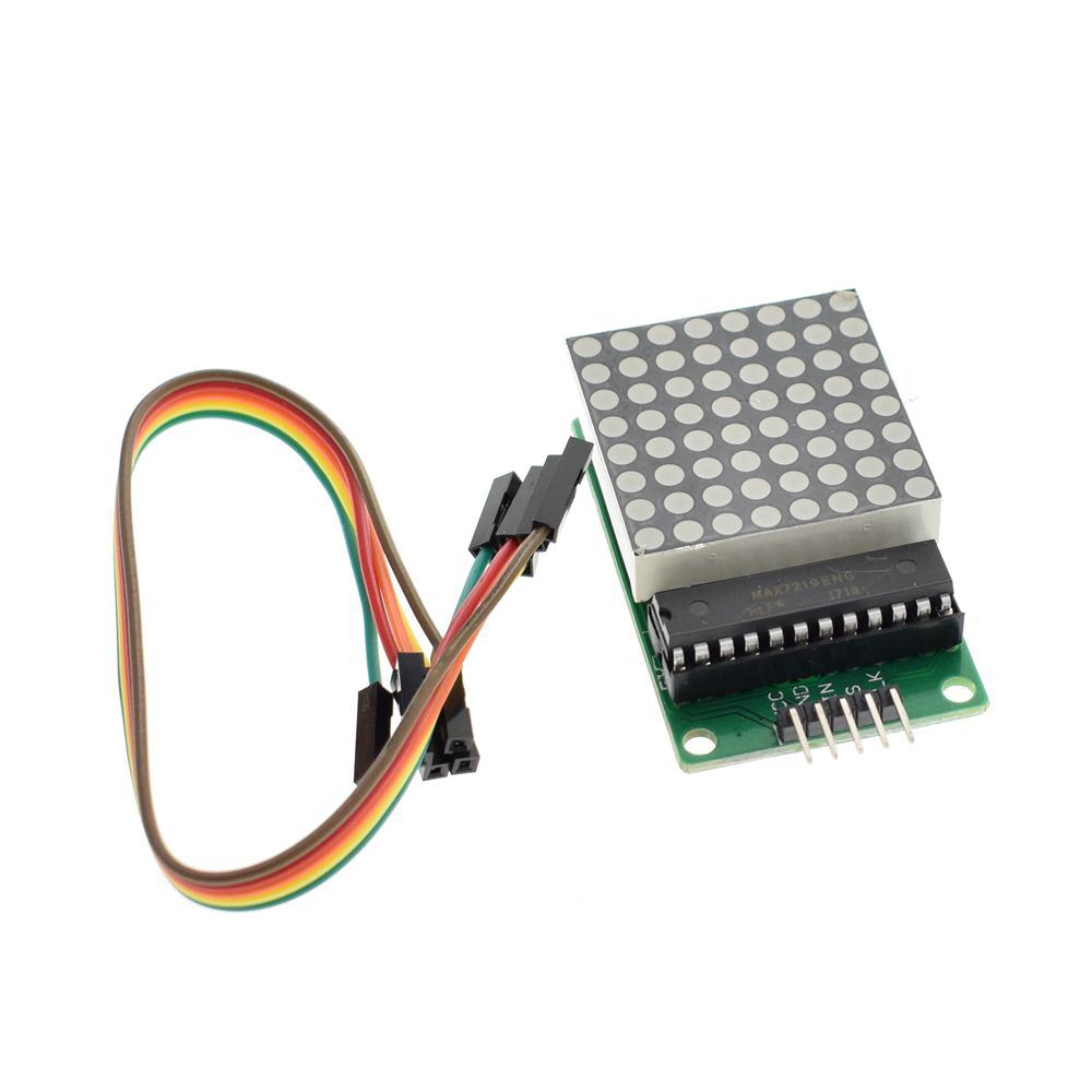
The DIY 8×8 Dot Matrix Display Module with MAX7219 Driver is a compact, powerful, and beginner-friendly LED display solution perfect for electronics hobbyists, educators, and makers. Whether you are just starting your journey into microcontrollers or looking to add visual output to advanced projects, this module offers an ideal platform for learning and creating.
At the heart of this module is the MAX7219 integrated circuit driver – a specialized serial input/output common-cathode display driver that dramatically simplifies the process of controlling LED matrices . The MAX7219 handles all the complex multiplexing and refresh timing internally, eliminating the need for constant microcontroller intervention and ensuring flicker-free display performance . The driver includes an 8×8 static RAM for storing display data, a BCD decoder, a multiplex scan circuit, and segment drivers—all integrated into a single chip.
The module communicates via a simple 3-wire or 4-wire SPI interface (VCC, GND, DIN, CS, CLK), requiring only three I/O pins from your microcontroller to control all 64 LEDs . This efficient communication protocol allows the module to be easily integrated with popular development platforms including Arduino, Raspberry Pi, ESP8266, ESP32, STM32, and other SPI-compatible microcontrollers.
The 8×8 LED matrix contains 64 red LEDs arranged in a grid, each individually controllable, enabling the display of custom characters, scrolling text, simple graphics, animations, and status indicators . The module is constructed on a durable PCB with four mounting holes, making it easy to secure to enclosures, panels, or custom mounting brackets.
Why choose this DIY module? The through-hole component design and clear PCB silkscreen make assembly straightforward, even for those new to soldering . The completed module provides a bright, reliable display that can be used in countless projects, from simple message boards to complex IoT status displays.
Whether you need to build a scrolling message board, a real-time data display for IoT projects, a scoreboard for sports events, a status indicator for industrial equipment, or simply want to add dynamic visual output to your next electronics project, this 8×8 Dot Matrix Display Module delivers reliable, bright, and easy-to-control LED display capability at an affordable price.
Assembly Required: This product is offered as a DIY kit. Some soldering is required to assemble the components onto the PCB. This is a great project for learning soldering skills and understanding electronics assembly .
Key Features
-
64 Individual LEDs – 8×8 dot matrix with each LED independently controllable for custom patterns and characters
-
MAX7219 Driver Chip – Handles all multiplexing and refresh timing automatically for flicker-free display
-
Simple SPI Interface – Only 3 I/O pins required to control all 64 LEDs (DIN, CS, CLK)
-
Software Brightness Control – 16 adjustable brightness levels via register setting (0x0 to 0xF)
-
Cascadable Design – Multiple modules can be daisy-chained to create larger displays
-
5V Operating Voltage – Compatible with 5V microcontrollers; 3.3V logic devices may require level shifting
-
Low Power Shutdown Mode – Consumes only 150µA in power-down mode
-
Through-Hole Components – Easy to solder, perfect for DIY assembly and learning
-
Library Support – Extensive community libraries available (LedControl, MD_Parola, MD_MAX72XX)
-
Compact Form Factor – Small PCB with mounting holes for secure installation
Technical Parameters
Usage Guide
Hardware Overview
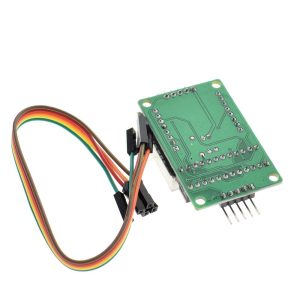
The MAX7219 8×8 Dot Matrix Module consists of an 8×8 LED matrix driven by a MAX7219 IC on a compact PCB. The module features input and output headers allowing multiple units to be cascaded easily .
Component Identification:
-
LED Panel: 8×8 LED matrix (64 LEDs total)
-
MAX7219 IC: Driver chip
-
Input Header (5 pins) : Connects to your microcontroller
-
Output Header (5 pins) : For cascading to additional modules
Pinout Description
The module uses a standard 5-pin header (2.54mm pitch) for connections :
Wiring Instructions
Step 1 – Connect to Microcontroller
Arduino Uno/Nano Connection:
ESP32/ESP8266 Connection:
Raspberry Pi Connection:
⚠️ Important: For Raspberry Pi and other 3.3V logic devices, the MAX7219 requires 5V power, but the logic signals (DIN, CS, CLK) should ideally be level-shifted from 3.3V to 5V for reliable operation.
Step 2 – Power Considerations
-
A single module draws approximately 320mA maximum when all LEDs are illuminated at full brightness
-
Most microcontroller 5V pins can supply 400-500mA, sufficient for one module
-
For cascaded modules or high-brightness applications, use an external 5V power supply
Cascading Multiple Modules
To create larger displays, connect additional modules in a daisy chain :
-
Connect the output header of the first module to the input header of the second module
-
Match pins: VCC→VCC, GND→GND, DIN→DOUT, CS→CS, CLK→CLK
-
Update the MAX_DEVICES parameter in your code to match the total number of modules
Cascading Example:
-
1 module = 8×8 pixels
-
2 modules = 8×16 pixels
-
4 modules = 8×32 pixels
Software Setup
Arduino – LedControl Library
-
Install Library: Open Arduino IDE → Tools → Manage Libraries → Search “LedControl” → Install
-
Basic Initialization Code:
#include "LedControl.h"
LedControl lc = LedControl(11, 13, 10, 1);
void setup() {
lc.shutdown(0, false);
lc.setIntensity(0, 8);
lc.clearDisplay(0);
}
void loop() {
lc.setLed(0, 0, 0, true);
delay(500);
lc.setLed(0, 0, 0, false);
delay(500);
}
Arduino – MD_Parola Library (Scrolling Text)
For advanced scrolling text effects, install both MD_Parola and MD_MAX72XX libraries :
#include <MD_Parola.h>
#include <MD_MAX72xx.h>
#include <SPI.h>
#define HARDWARE_TYPE MD_MAX72XX::FC16_HW
#define CS_PIN 10
#define MAX_DEVICES 1
MD_Parola display = MD_Parola(HARDWARE_TYPE, CS_PIN, MAX_DEVICES);
void setup() {
display.begin();
display.setIntensity(8);
display.displayClear();
}
void loop() {
display.displayScroll("Hello!", PA_CENTER, PA_SCROLL_LEFT, 100);
while (!display.displayAnimate()) { }
delay(1000);
}
Important Note on Hardware Type: If the displayed text appears reversed or upside down, change the HARDWARE_TYPE definition :
-
#define HARDWARE_TYPE MD_MAX72XX::FC16_HW (most common)
-
#define HARDWARE_TYPE MD_MAX72XX::PAROLA_HW
-
#define HARDWARE_TYPE MD_MAX72XX::GENERIC_HW
Character Display Patterns
To display custom characters, define byte arrays for each row (1 = LED ON, 0 = LED OFF) :
byte smiley[8] = {
B00111100,
B01000010,
B10100101,
B10000001,
B10100101,
B10011001,
B01000010,
B00111100
};
for (int row = 0; row < 8; row++) {
lc.setRow(0, row, smiley[row]);
}
Assembly Instructions (DIY Kit Version)
This module is offered as a DIY kit. Basic soldering is required :
-
Identify Components: Check that all components are present (PCB, MAX7219 IC, 8×8 LED matrix, resistors, capacitors, pin headers)
-
Start with Low-Profile Components: Solder resistors and capacitors first
-
Install the MAX7219 IC: Pay attention to orientation – the notch or dot indicates pin 1
-
Install the LED Matrix: Ensure correct orientation. The matrix has a polarity – if LEDs don’t light as expected after assembly, the matrix may need to be rotated 180°
-
Install Pin Headers: Solder the 5-pin input header and optional output header
-
Inspect Solder Joints: Check for cold solder joints or bridges
-
Test the Module: Power on and run a simple test sketch before final installation
Installation Tips
-
Mounting: Secure using M3 screws through the four corner mounting holes
-
Ventilation: Ensure adequate airflow around the module, especially in cascaded configurations
-
Cable Length: Keep SPI wires as short as possible (under 50cm) to prevent signal degradation
-
Level Shifting: For 3.3V microcontrollers, use a 4-channel bi-directional logic level converter
-
Enclosure: For outdoor installations, protect the module in a weatherproof enclosure
Q: Do I need to assemble this module myself?
Yes. This product is offered as a DIY kit. Some soldering is required to assemble the components onto the PCB . This is a great project for learning soldering skills and understanding electronics assembly.
Q: Is this module compatible with Arduino?
Yes. The MAX7219 module is fully compatible with Arduino and is one of the most popular displays used in Arduino projects . The LedControl and MD_Parola libraries provide easy-to-use functions for controlling the display.
Q: Can I use this module with Raspberry Pi?
Yes. The module can be used with Raspberry Pi. However, note that the MAX7219 requires 5V power, and Raspberry Pi GPIO pins are 3.3V logic. While some users report success without level shifting, it is recommended to use a logic level converter for the DIN, CS, and CLK signals for reliable operation
Q: What is the difference between the red, green, and blue versions?
The driver IC and electrical specifications are identical across all versions. The only difference is the LED color:
-
Red: Classic display color; often more visible in bright ambient light; lower power consumption typically
-
Green: Excellent visibility in both bright and dim lighting conditions due to human eye sensitivity
-
Blue: Modern, high-tech aesthetic; effective in low-light environments
Q: How do I control the brightness?
Brightness can be adjusted in software using:
-
LedControl: lc.setIntensity(addr, value) where value = 0 (min) to 15 (max)
-
MD_Parola: display.setIntensity(value)
The MAX7219 supports 16 discrete brightness levels
Q: What is the maximum current draw?
-
Normal operation: approximately 30-80mA
-
All 64 LEDs at maximum brightness: up to 320mA
-
For cascaded modules, total current adds: 4 modules could draw over 1.2A at full brightness
-
For multiple modules, use an external 5V power supply
Q: Can I cascade multiple modules together?
Yes. Connect the output header of one module to the input header of the next . Update the MAX_DEVICES parameter in your code to match the total number of modules. Most SPI setups support up to 8 modules before signal timing becomes an issue
Q: Can I use this module for both home and business applications?
Home users: DIY message boards, IoT status displays, clock projects, home automation status indicators, retro game displays, custom scoreboards.
Business users: Retail signage (scrolling promotions), industrial equipment status displays, public transportation information boards, queue management displays, laboratory equipment readouts.
Q: Does the module remember the display content after power loss?
No. The MAX7219 has volatile memory. When power is lost, the display content is cleared. Your microcontroller must re-send display data during startup.
Q: Why does my text display backwards or upside down?
This is a common issue caused by incorrect hardware type definition in the MD_Parola library. Try changing the HARDWARE_TYPE definition:
-
#define HARDWARE_TYPE MD_MAX72XX::FC16_HW (most common)
-
#define HARDWARE_TYPE MD_MAX72XX::PAROLA_HW
-
#define HARDWARE_TYPE MD_MAX72XX::GENERIC_HW