Product Description
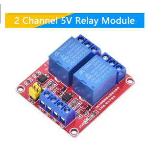
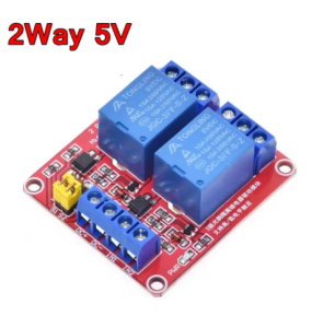
The Dual-Channel 5V Opto-Isolated Relay Module is a premium, compact switching solution engineered for applications where electrical integrity and signal protection are paramount. This module combines the robust power-handling capability of industrial relays with the critical safety feature of optical isolation, creating a reliable bridge between your sensitive 5V microcontroller and high-power AC/DC loads. Each of its two independent channels is equipped with a dedicated optocoupler, establishing a complete 2500V electrical barrier that blocks harmful voltage spikes, ground loops, and electrical noise from the load side, ensuring your Arduino, Raspberry Pi, or PLC remains safe and operational.
Designed for maximum flexibility, the module features a simple jumper to select between high-level or low-level trigger logic for each channel, making it universally compatible with any digital control system. The inclusion of dual status LEDs per channel—one for opto activation and one for relay state—provides unparalleled diagnostic clarity. With its high-current relay contacts, secure screw terminals, and compact footprint, this module is the ideal choice for projects that require a reliable, protected, and versatile two-channel interface, from sophisticated prototyping to final product integration in noise-sensitive environments.
Key Features
-
Dual Optical Isolation: Each channel is protected by an independent optocoupler, providing 2500Vrms of isolation to safeguard your control electronics from high-voltage transients and noisy load circuits.
-
Selectable Trigger Logic: A simple jumper allows you to configure each channel for either High-Level (active-HIGH) or Low-Level (active-LOW) trigger, ensuring perfect compatibility with any microcontroller or control logic.
-
Two High-Capacity Relay Channels: Features two industrial-grade electromagnetic relays with SPDT contacts, each capable of switching up to 10A loads, suitable for a wide range of AC and DC applications.
-
Comprehensive Status Indication: Two LEDs per channel provide clear visual feedback: one indicates the opto-isolator is activated by the input signal, and the other shows the physical state of the relay coil and contacts.
-
Integrated Voltage Spike Protection: Each relay coil is fitted with a flyback diode to suppress inductive kickback, protecting the drive transistor and ensuring long-term circuit reliability.
-
5V TTL Logic Compatible: Designed for direct, easy interfacing with 5V microcontrollers like Arduino, requiring only a minimal current draw to activate the opto-isolators.
-
Secure & Professional Connections: All high-power load connections utilize reliable screw terminals, while control connections are made via a standard pin header for a clean setup.
-
Compact & Robust Design: Built with high-quality components on a durable PCB, offering professional performance in a minimal footprint ideal for space-constrained projects.
Main Parameters
-
Channels: 2 Independent Relays
-
Control Signal Logic: 5V TTL
-
Trigger Mode: High or Low Level (Jumper Selectable)
-
Isolation Rating: 2500V RMS (Optocoupler)
-
Relay Contact Rating: 10A @ 250VAC / 10A @ 30VDC
-
Relay Type: Electromagnetic, SPDT (Single Pole Double Throw)
-
Input Current (per channel): ~5-10mA (to activate optocoupler)
-
Dimensions: Approx. 80mm x 55mm x 20mm
Typical Applications / Usage
-
Industrial Sensor/Actuator Interface: Safely connect PLC outputs or sensor signals to control industrial actuators, solenoid valves, or small motors in electrically noisy factory environments.
-
Protected Appliance Control: Build a reliable interface for smart home projects, using a microcontroller to safely control two high-power appliances (e.g., a lamp and a fan) without risk to the controller.
-
Audio/Video Equipment Control: Create noise-free switching for controlling equipment racks, where ground loops can introduce hum, by using the optical isolation to break the ground connection between devices.
-
Automotive & Marine Electronics: Interface vehicle microcontrollers with high-power accessories (light bars, winches, pumps) while providing a critical barrier against the vehicle’s noisy 12/24V electrical system.
-
Laboratory & Measurement Setups: Integrate into sensitive test equipment where the switching of loads must not introduce electrical noise that could interfere with measurement accuracy.
-
Prototyping Reliable Products: The perfect choice for developing and prototyping commercial or industrial products where safety, reliability, and noise immunity are essential design criteria.
Connection & Configuration Guide:
-
Trigger Configuration: For each channel, place the jumper cap over the pins labeled “H” for High-Level trigger (relay activates on a 5V signal) or “L” for Low-Level trigger (relay activates on a 0V signal).
-
Power & Control Wiring: Connect the module’s VCC and GND to a 5V DC power source. Connect the two signal pins (IN1, IN2) to the digital output pins of your microcontroller. The low input current (~5-10mA per channel) makes it easy to drive.
-
Load Wiring: Connect the power source (AC Mains or DC) for your device to the relay’s Common (COM) terminal. Connect the device to be controlled to the Normally Open (NO) terminal to power it when the relay activates. SAFETY FIRST: Always disconnect all high-voltage power before making connections. Install the module in a proper insulated enclosure.
Q: Why should I choose an opto-isolated module over a standard relay module?
Opto-isolation is critical for safety and reliability when your control circuit and the load circuit use separate power supplies or are in electrically noisy environments. It prevents damaging voltage spikes, ground loops, and interference from traveling back to your microcontroller, which can cause resets, malfunctions, or permanent damage.
Q: How do I decide between High-Level and Low-Level trigger?
The choice depends on your controller’s default logic and safety requirements.
-
Use High-Level (H) if your code uses digitalWrite(pin, HIGH);to turn something ON (common with Arduino).
-
Use Low-Level (L) for “sinking” logic or for a fail-safe design, as a broken control wire will default to a HIGH state (if pulled up), turning the relay OFF.
Q: Can I use this with a 3.3V device like an ESP32 or Raspberry Pi?
Yes, typically for High-Level trigger mode. While the module’s VCC should be 5V, a 3.3V HIGH signal is often sufficient to activate the optocoupler’s LED. For guaranteed operation, set the jumper to “H” and test. Using a logic level converter is the most reliable method for 3.3V systems.
Q: What is the purpose of the "JD-VCC" jumper or pin?
This pin allows you to power the relay coils from a separate 5V power supply. This is highly recommended if you are switching the relays frequently or using high-current loads, as it prevents the coil inrush current from causing a voltage drop on your sensitive microcontroller’s 5V line. Connect your external 5V supply to JD-VCC and GND.
Q: What do the two different LEDs on each channel indicate?
-
The smaller LED (near the IN pin): Lights when the optocoupler receives a valid trigger signal. It shows your control command has been received by the isolation barrier.
-
The larger LED (near the relay): Lights when the relay coil is energized and the physical contacts have closed. It confirms the output has switched.
Q: Can I switch a DC load, like a 12V motor, and an AC load, like a 120V lamp, at the same time?
Yes, you can. The relay contacts are rated for both AC and DC. You can use one channel for a DC motor and the other for an AC lamp, as they are completely independent. Never exceed the 10A and 250VAC/30VDC ratings per channel.
Q: The relay makes a soft "click" but the status LED doesn't light. What's wrong?
If you hear the relay click but the relay status LED (not the opto LED) doesn’t light, the issue is likely on the load side. Check that your load wiring is correct, the device works, and that power is actually present at the COM terminal. The click confirms the coil is energized, but the LED for the relay is often powered from the load-side voltage.
Q: Is this module suitable for business or light industrial integration?
Absolutely. Its combination of optical isolation, robust relay ratings, professional terminals, and flexible triggering makes it an excellent, reliable component for integration into commercial products, industrial control sub-assemblies, kiosks, and custom automation solutions. We offer volume pricing and support for business clients.