Product Overview
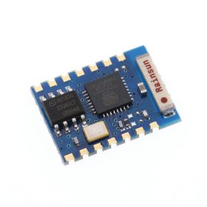
The ESP8266-03 WiFi Module is a compact, high-performance wireless transceiver designed for seamless integration into IoT and embedded systems. As a member of the acclaimed ESP8266 family from Espressif Systems, the ESP-03 variant offers a compelling balance of size, performance, and connectivity features, making it an ideal choice for both DIY hobbyists and industrial IoT applications .
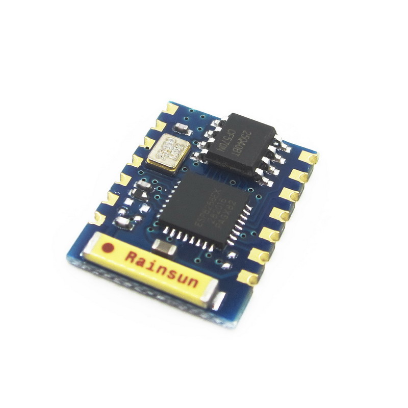
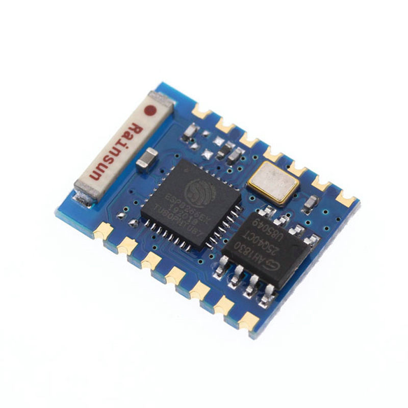
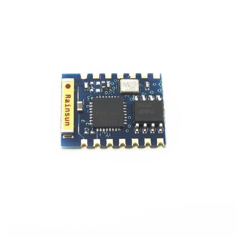
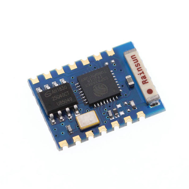
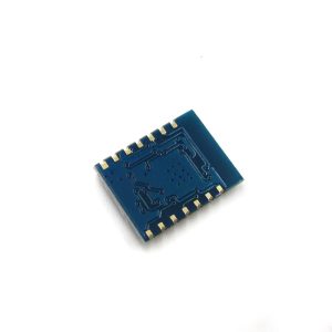
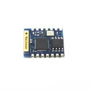
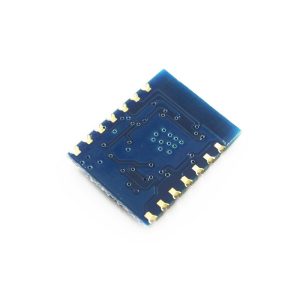
Distinguished by its onboard ceramic antenna and SMD (Surface Mount Device) form factor, the ESP-03 delivers superior wireless range and stability compared to basic PCB-antenna modules, while maintaining a compact footprint perfect for space-constrained designs . It is built around the powerful ESP8266EX chip—a 32-bit RISC processor with integrated Wi-Fi (802.11 b/g/n), a full TCP/IP stack, and ample memory for complex applications .
The module functions as a complete system-on-chip (SoC), capable of running application code independently without an external microcontroller. With 14 castellated pins providing access to 7 GPIOs, UART, SPI, I2C, and ADC interfaces, the ESP-03 can directly interface with sensors, relays, displays, and actuators . Whether you are building a smart lighting system, a wireless environmental monitor, an industrial gateway, or a custom automation controller, the ESP-03 provides a robust, low-power, and developer-friendly platform.
Key Features
-
Powerful 32-bit Processor: Built around the Tensilica L106 32-bit RISC processor running at up to 160 MHz, providing ample processing power for complex IoT applications without requiring an external microcontroller .
-
Integrated Wi-Fi Connectivity: Supports 802.11 b/g/n protocols at 2.4 GHz with integrated TR switch, balun, LNA, power amplifier, and matching network. Delivers up to +19.5dBm output power for reliable wireless communication .
-
Superior Onboard Ceramic Antenna: Features a high-performance ceramic antenna that provides better range and signal stability than PCB trace antennas, while maintaining a compact form factor .
-
Rich I/O Capabilities: Provides 7 GPIO pins (GPIO0, GPIO2, GPIO12, GPIO13, GPIO14, GPIO15, and GPIO18) with support for UART, SPI, I2C, PWM, and 10-bit ADC, allowing connection to a wide variety of sensors, actuators, and display devices .
-
Sufficient Flash Memory: Equipped with 4 MB (32 Mbit) of flash memory, providing ample storage for firmware, web interfaces, and OTA (Over-The-Air) firmware updates .
-
Multiple Operating Modes: Supports Station (STA), Access Point (AP), and Station+AP modes, enabling devices to connect to existing networks or create their own .
-
Ultra-Low Power Consumption: Features multiple sleep modes with deep sleep current as low as 10 µA and standby power consumption less than 1.0 mW (DTIM3). Wake up and transmit packets in less than 2 ms, making it ideal for battery-powered applications .
-
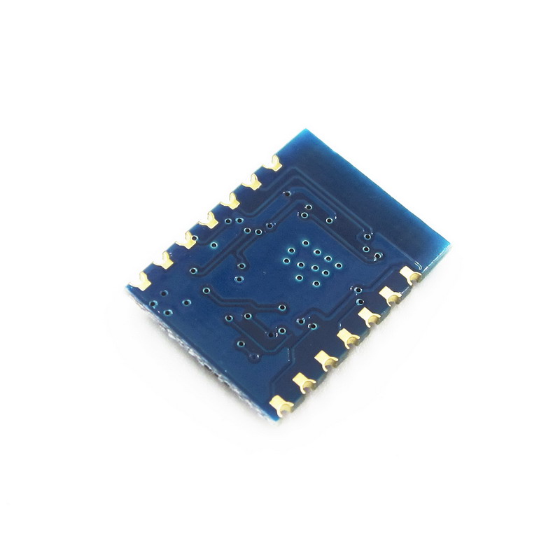
SMD Package for Professional Integration: The 14-pin SMD form factor with castellated edges is designed for automated surface-mount assembly, making it suitable for large-scale production while remaining accessible for hand soldering .
-
Developer-Friendly: Fully supported in Arduino IDE, MicroPython, NodeMCU (Lua), and ESP-IDF. A vast online community provides extensive libraries, code examples, and project tutorials .
-
Smart Configuration Support: Compatible with Smart Config and AirKiss one-click network configuration technologies, simplifying device onboarding for Android and iOS devices .
-
Comprehensive Security: Supports WEP/WPA/WPA2-PSK security protocols, ensuring secure wireless communication.
Technical Specifications
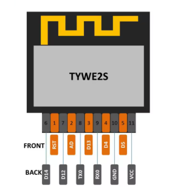
Pinout & Interface Guide
The ESP-03 features a 14-pin SMD package with castellated edges for easy soldering. The pin configuration is as follows :
Boot Mode Configuration
The ESP-03’s boot mode is determined by the state of GPIO0, GPIO2, and GPIO15 :
Critical Notes:
-
GPIO15 must be pulled LOW during boot for both modes
-
GPIO2 must be pulled HIGH during boot
-
GPIO0 must be LOW to enter programming mode, HIGH for normal operation
Usage Guide
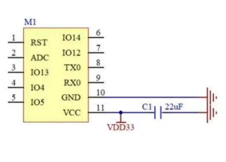
Power Supply Requirements
The ESP-03 requires a stable 3.3V DC power supply capable of providing at least 300mA during peak operation. For reliable operation:
-
Use a low-dropout regulator (LDO) such as AMS1117-3.3 or LM1117-3.3
-
Add a 10µF to 100µF electrolytic capacitor and a 0.1µF ceramic capacitor close to the VCC pin for power decoupling
-
Do not apply 5V to any pin—this will permanently damage the module
Programming the ESP-03
Method 1: Using a USB-to-TTL Adapter
This is the simplest method for programming the module:
Enter Programming Mode:
-
Connect GPIO0 (pin 10) to GND
-
Connect GPIO15 (pin 5) to GND
-
Connect GPIO2 (pin 7) to VCC (pull HIGH)
-
Connect CH_PD (pin 8) to VCC (pull HIGH)
-
Apply power or pulse RST LOW (pin 14)
-
Upload firmware via Arduino IDE or esptool
-
After upload, disconnect GPIO0 from GND and reset
Setting Up Arduino IDE for ESP-03
-
Install ESP8266 Board Package:
-
Open Arduino IDE → File → Preferences
-
Add to “Additional Boards Manager URLs”: https://arduino.esp8266.com/stable/package_esp8266com_index.json
-
Tools → Board → Boards Manager → Search “esp8266” → Install
-
Select Board:
-
Configure Flash Settings:
Basic Arduino Example Code
#include <ESP8266WiFi.h>
const char* ssid = "your_SSID";
const char* password = "your_PASSWORD";
void setup() {
Serial.begin(115200);
Serial.println("\nESP-03 Wi-Fi Test");
WiFi.begin(ssid, password);
Serial.print("Connecting to Wi-Fi");
while (WiFi.status() != WL_CONNECTED) {
delay(500);
Serial.print(".");
}
Serial.println("\nConnected successfully!");
Serial.print("IP Address: ");
Serial.println(WiFi.localIP());
}
void loop() {
}
AT Command Example
With the default AT firmware, the ESP-03 can be controlled via simple serial commands at 115200 baud :
AT                    // Check communication
AT+GMR                // Check firmware version
AT+CWMODE=1           // Set to Station mode
AT+CWJAP="SSID","PASSWORD"  // Connect to Wi-Fi
AT+CIFSR              // Get IP address
AT+CIPSTART="TCP","192.168.1.100",80  // Open TCP connection
AT+CIPSEND=5          // Send data
> HELLO                // Data to send
Development Environments
-
Arduino IDE: User-friendly environment with extensive libraries
-
PlatformIO: Professional development environment with ESP8266 support
-
ESP-IDF: Official Espressif development framework for advanced users
-
MicroPython: Python-based development for rapid prototyping
-
NodeMCU: Lua-based firmware for quick project development
Typical Applications
The ESP-03 is widely used in :
-
Smart Home: Lighting control, smart plugs, thermostats, window/door sensors
-
Industrial Automation: Equipment monitoring, data collection, predictive maintenance
-
Environmental Monitoring: Temperature, humidity, air quality sensors
-
Wearable Electronics: Health monitoring devices, location tags
-
Wireless Positioning Systems: Asset tracking, indoor navigation
-
Remote Control Systems: Industrial machinery control, robotics
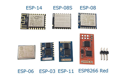
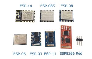
Q: What is the difference between ESP-01 and ESP-03?
The ESP-03 offers several advantages over the ESP-01 :
-
More GPIO pins: 7 GPIOs vs. 2 on the ESP-01
-
More flash memory: 4MB vs. 512KB-1MB on the ESP-01
-
Superior antenna: Onboard ceramic antenna for better range and signal stability
-
SMD package: Designed for automated assembly
-
More clients supported: Up to 64 client connections vs. 16 on ESP-01
Q: Can the ESP-03 operate as a standalone microcontroller?
Yes. The ESP8266EX chip includes a 32-bit processor capable of running application code directly. You can program it with Arduino, MicroPython, or the ESP8266 SDK without requiring an external microcontroller
Q: How many GPIO pins are available on the ESP-03?
The ESP-03 provides 7 usable GPIO pins (GPIO0, GPIO2, GPIO12, GPIO13, GPIO14, GPIO15, GPIO16). Note that GPIO18 is also available on some pinout versions
Q: What is the maximum range of the ESP-03's Wi-Fi connection?
Thanks to its ceramic antenna, the ESP-03 achieves better range than PCB-antenna modules. In open space, ranges up to 100-200 meters are achievable. In practical indoor applications with walls and obstacles, the range is typically 30-50 meters.
Q: Does the ESP-03 support Bluetooth?
No. The ESP8266 series is Wi-Fi only. For Bluetooth capability, consider the ESP32 series.
Q: What voltage does the ESP-03 require?
The ESP-03 requires a stable 3.3V DC power supply. The operating range is 3.0V to 3.6V . Never apply 5V to the VCC pin or any GPIO pin—this will destroy the module.
Q: How much current does the ESP-03 draw?
Current consumption varies by operating mode :
Q: Can I power the ESP-03 with batteries?
Yes. The ESP-03’s low power consumption makes it suitable for battery-powered applications. A single 18650 lithium-ion cell (3.7V) can be used with a 3.3V LDO regulator . With proper deep sleep management, battery life of months is achievable.
Q: Why does my ESP-03 not boot?
Common boot issues include :
-
GPIO15 not pulled LOW during boot
-
GPIO0 pulled LOW (this enters programming mode)
-
GPIO2 not pulled HIGH during boot
-
CH_PD/EN not connected to VCC
-
Insufficient power supply (current sag during startup)
Q: How do I put the ESP-03 into programming mode?
To enter programming (UART download) mode:
-
Pull GPIO0 LOW (connect to GND)
-
Pull GPIO15 LOW (connect to GND)
-
Pull GPIO2 HIGH (connect to VCC)
-
Pull CH_PD HIGH (connect to VCC)
-
Apply power or pulse RST LOW
Q: Why can't I upload code to my ESP-03?
Common upload issues:
-
GPIO0 not held LOW during power-on/reset
-
Incorrect serial connections (TX to RX, RX to TX)
-
Insufficient power supply (USB-to-TTL adapters may not provide enough current)
-
Wrong board selection in Arduino IDE (select “Generic ESP8266 Module”)
-
Missing pull-down on GPIO15
Q: What is the baud rate for programming?
The ESP-03 communicates at 115200 baud for programming by default , though the bootloader outputs diagnostic information at 74880 baud. For reliable programming, use 115200 baud.
Q: Can I use the ESP-03 with Arduino IDE?
Yes. Install the ESP8266 board package via Boards Manager, then select “Generic ESP8266 Module” as the board. Configure the flash size (4MB) and upload speed appropriately
Q: What is the difference between deep sleep and normal operation?
Deep sleep is an ultra-low power mode that shuts down most of the module’s functions, reducing current consumption to <10µA . The module can wake up and transmit packets in less than 2 ms, making it ideal for battery-powered applications that only need to transmit data intermittently.
Q: What can I build with the ESP-03?
Popular applications include :
-
Smart home devices: Lighting control, smart plugs, thermostats, window/door sensors
-
Environmental monitoring: Temperature, humidity, air quality stations
-
Industrial wireless sensors: Equipment monitoring, predictive maintenance
-
Wearable electronics: Health monitors, location tags
-
Remote data logging: Weather stations, agricultural sensors
-
Wireless control systems: Remote machinery control, robotics
Q: Is the ESP-03 suitable for commercial products?
Yes. The ESP-03’s SMD package is designed for automated assembly, and its industrial temperature rating makes it suitable for commercial and industrial products . However, note that it has fewer GPIO pins than newer modules like ESP-12F.
Q: What firmware options are available?
Popular firmware choices include:
-
AT Command Firmware: Default firmware for co-processor mode
-
NodeMCU (Lua): Open-source Lua-based firmware for easy programming
-
MicroPython: Python-based development for rapid prototyping
-
Arduino/C++: Custom code via Arduino IDE
-
ESP-IDF: Official Espressif development framework
Q: Does the ESP-03 support OTA (Over-The-Air) updates?
Yes. The 4MB flash memory supports OTA firmware updates, allowing you to upload new code wirelessly without physically connecting to the module