Description
Product Overview
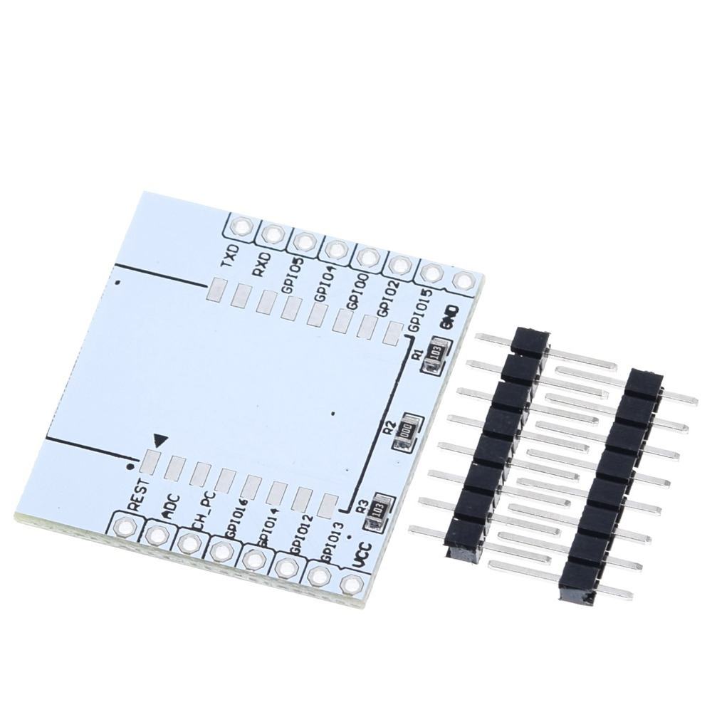
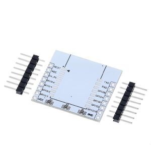
The ESP8266 Serial WiFi Module Adapter Plate is an essential breakout board designed to solve the common problem of working with SMD (Surface Mount Device) ESP8266 modules such as the ESP-07, ESP-08, and ESP-12E. These popular Wi-Fi modules feature an unfriendly 2mm pin pitch that is incompatible with standard breadboards (which use 2.54mm spacing) and difficult to solder for prototyping .
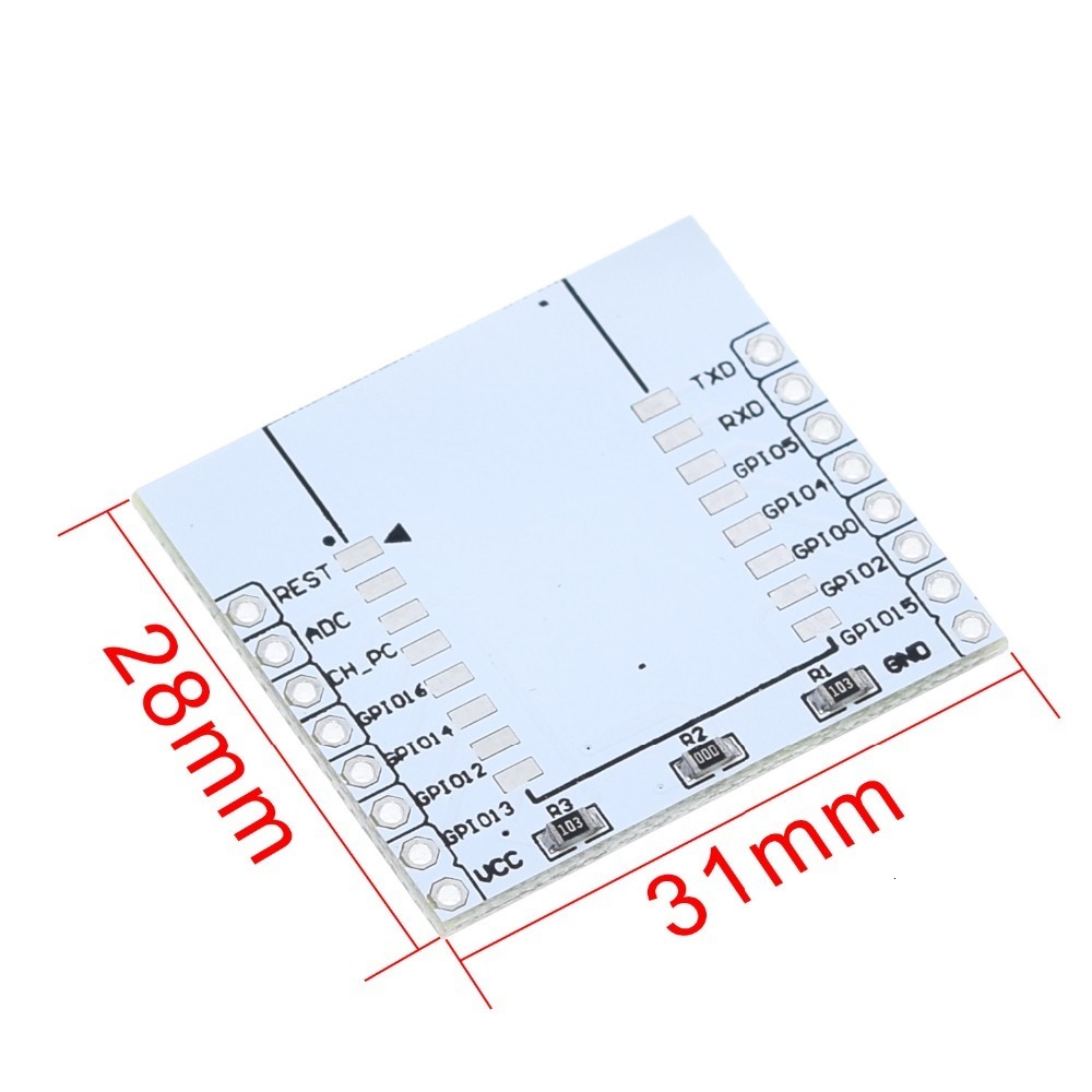
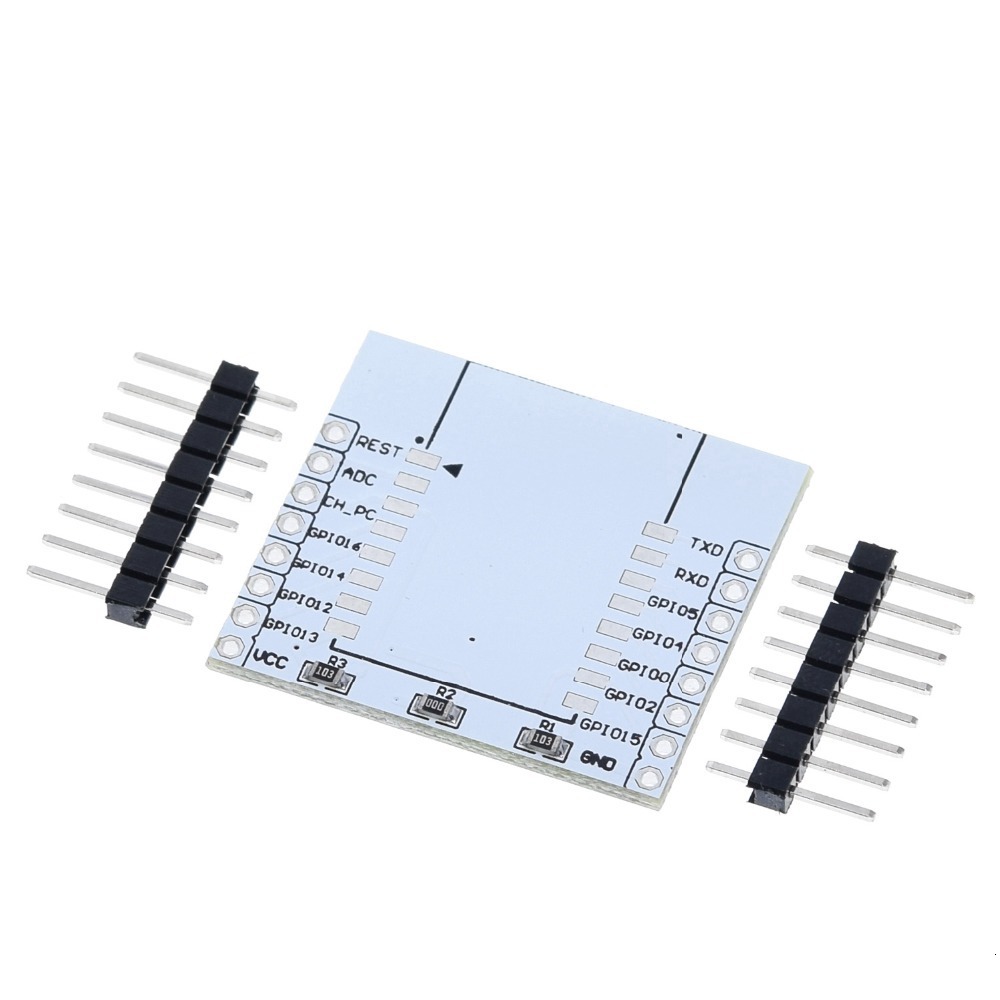
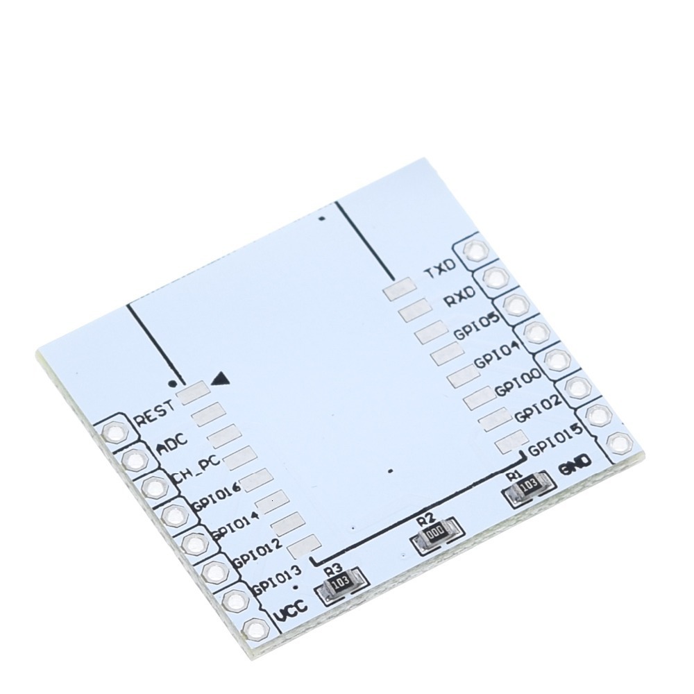
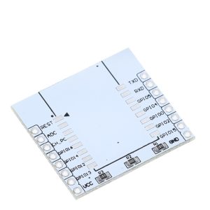
This adapter plate transforms these SMD modules into a breadboard-friendly format, converting the 2mm pitch to the standard 2.54mm spacing used by breadboards, perfboards, and standard jumper wires . The WiFi module solders directly to the adapter, with clearly labeled pinouts on the top layer for easy identification and connection .
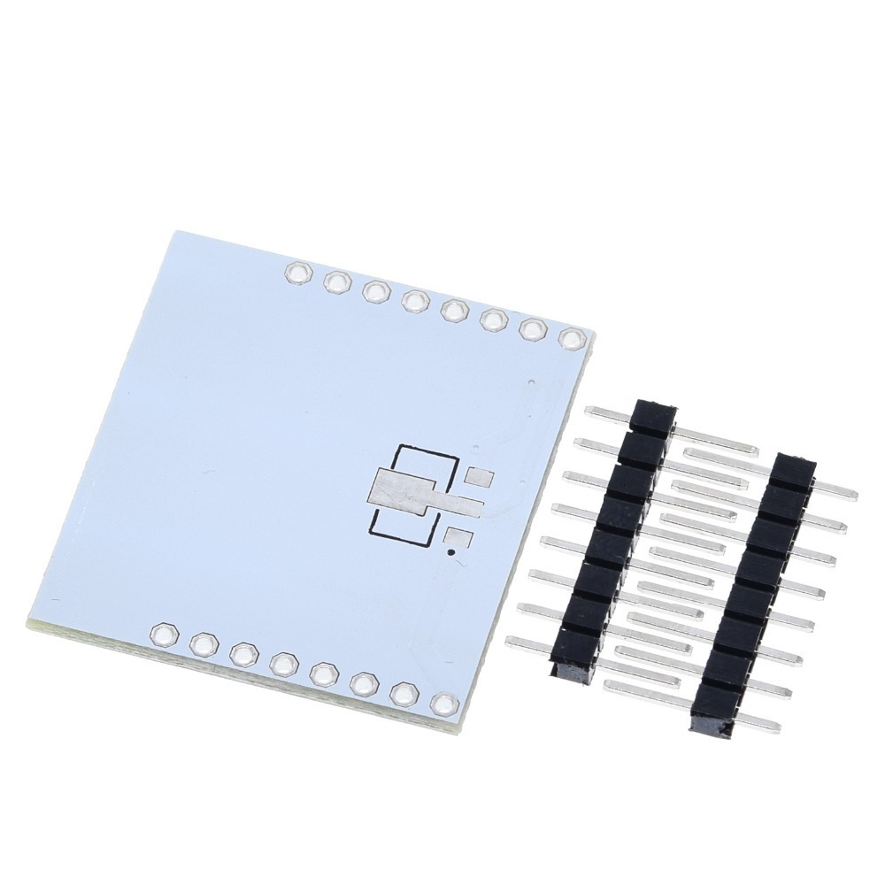
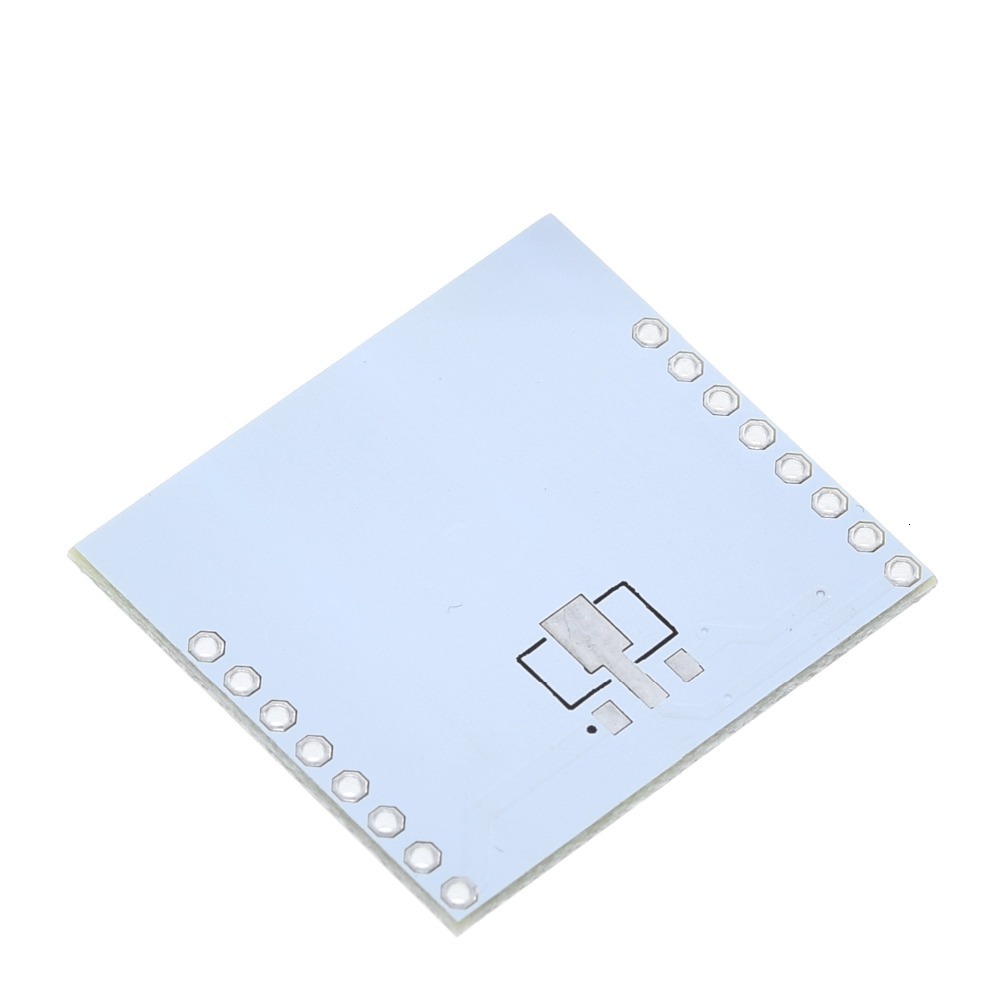
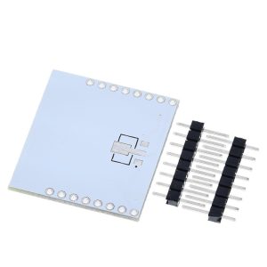
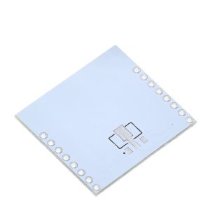
Beyond simple pin conversion, the adapter plate includes thoughtful engineering features to simplify your project. It features a reserved land-pattern for a 3.3V voltage regulator on the bottom layer, allowing you to add onboard voltage regulation if needed . A pre-populated 10K pull-up resistor ensures proper chip operation by connecting CH_PD (Chip Enable) to VCC . Additionally, GPIO15 is connected to GND to facilitate normal flash boot mode, eliminating one of the common wiring errors when working with ESP8266 modules .
Whether you are a hobbyist prototyping on a breadboard, an educator building classroom kits, or a business developing custom IoT products, this adapter plate provides a reliable, reusable platform for integrating ESP8266 Wi-Fi modules into your projects without the hassle of custom PCB design.
Key Features
-
Pin Pitch Conversion: Converts the 2mm pin pitch of ESP-07/08/12 modules to the standard 2.54mm (0.1-inch) breadboard-friendly spacing, allowing direct use with breadboards, perfboards, and standard jumper wires .
-
Wide Module Compatibility: Compatible with multiple ESP8266 SMD modules including ESP-07, ESP-08, ESP-12, ESP-12E, and ESP-12F .
-
Reserved 3.3V Voltage Regulator Land-Pattern: Features a dedicated area on the bottom layer for soldering a 3.3V voltage regulator (e.g., AMS1117-3.3). When the 0Ω jumper resistor is removed, the VCC pin accepts 4.5V–9V input, which is regulated down to 3.3V for the module .
-
Pre-Populated Pull-Up Resistor: Includes a 10K pull-up resistor between CH_PD (Chip Enable) and VCC to ensure the chip is properly enabled during normal operation .
-
Integrated Boot Configuration: GPIO15 is connected to GND on the PCB, which is required for proper boot mode operation, eliminating one common wiring error .
-
Clear Pin Labeling: Pinouts are clearly printed on the top layer of the PCB in black for easy identification and connection .
-
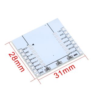
Compact and Durable Design: PCB dimensions approximately 27mm × 30mm × 1.6mm, with a sturdy white or black solder mask finish .
-
Ideal for Prototyping: Perfect for use with breadboards, perfboards, and for creating reusable module sockets for multiple projects.
Technical Specifications
| Parameter | Operating Value |
|---|---|
| Compatible Modules | ESP-07, ESP-08, ESP-12, ESP-12E, ESP-12F |
| Input Pin Pitch (Module Side) | 2mm |
| Output Pin Pitch (Adapter Side) | 2.54mm (0.1 inch) |
| Board Dimensions (Approx.) | 27mm × 30mm × 1.6mm |
| PCB Thickness | 1.6mm |
| Weight | Approx. 4g |
| Onboard Components | 10K pull-up resistor (CH_PD to VCC), 0Ω jumper resistor (R1/R2 for regulator bypass) |
| Bottom Layer Feature | Land-pattern for 3.3V voltage regulator (LDO) |
| Board Color | White, black, or green (varies by manufacturer) |
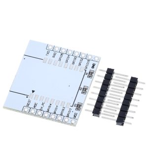
| Mounting | Standard 2.54mm header pins (included, not soldered) |
Reviews
There are no reviews yet.