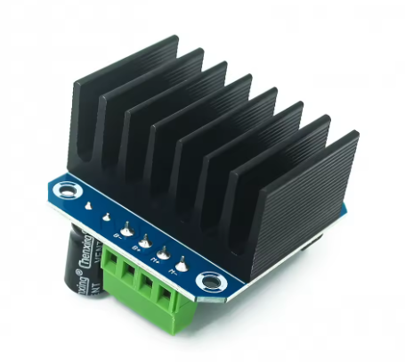
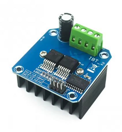
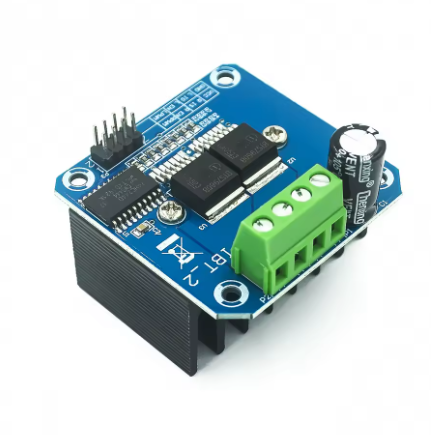
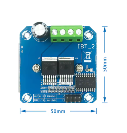
Product Overview
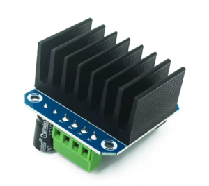
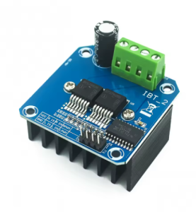
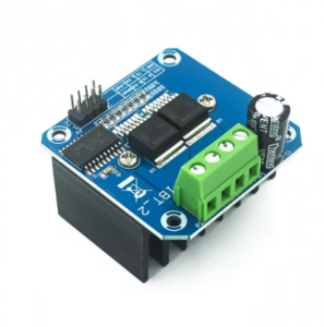
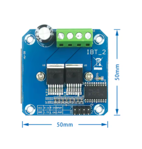
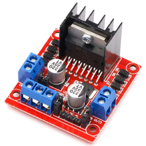
The High-Power Smart Car Motor Driver Module is a professional-grade H-bridge driver board designed for demanding DC motor control applications. Built around the Infineon BTS7960 high-current half-bridge NovalithIC, this module delivers exceptional power handling capability with integrated protection features, making it the ideal choice for robotics, smart cars, industrial automation, and electric vehicle projects .
The BTS7960 is a fully integrated high-current half-bridge driver that combines a p-channel high-side MOSFET and an n-channel low-side MOSFET with a dedicated driver IC in a single package. This unique architecture eliminates the need for a charge pump, significantly reducing electromagnetic interference (EMI) and simplifying circuit design . By using two BTS7960 ICs in parallel, the module forms a complete H-bridge capable of driving high-power DC motors in both directions with smooth PWM speed control.
What sets this module apart is its comprehensive protection system and 43A current limit capability. The built-in current limitation actively monitors and limits output current to approximately 43A, protecting both the driver and the motor from damage during overload or stall conditions . Additionally, the module features overtemperature shutdown, overvoltage lockout, undervoltage protection, and short circuit protection, ensuring reliable operation even in demanding environments.
The module supports PWM frequencies up to 25kHz, enabling smooth and efficient motor speed control. Logic-level inputs (3.3V to 5V compatible) allow direct connection to Arduino, ESP32, STM32, Raspberry Pi, and other microcontrollers without level shifters . Onboard current sense outputs provide real-time current monitoring and fault diagnosis capabilities, making this module suitable for both educational projects and professional industrial applications.
Key Features
-
43A Peak Current Capability: The module features a typical current limitation level of 43A, allowing it to drive high-torque DC motors used in robotics, e-bikes, and industrial automation .
-
Integrated H-Bridge Configuration: Uses two BTS7960 half-bridge ICs to form a complete H-bridge, enabling bidirectional motor control with forward, reverse, and brake functions .
-
Ultra-Low Path Resistance: Typical path resistance of only 16 mΩ at 25°C ensures minimal power loss and heat generation during high-current operation .
-
Wide Operating Voltage Range: Accepts input voltages from 6V to 27V DC, making it compatible with 6V, 12V, and 24V battery systems .
-
PWM Speed Control Support: Capable of PWM frequencies up to 25 kHz, with active freewheeling for smooth motor speed regulation and reduced switching losses .
-
Comprehensive Protection Features: Includes overtemperature shutdown (with latch behavior), overvoltage lockout, undervoltage shutdown, overcurrent/short-circuit protection, and switched-mode current limitation .
-
Low Quiescent Current: Consumes only 7 µA typical at 25°C when idle, making it suitable for battery-powered applications .
-
Logic-Level Inputs: Control inputs accept 3.3V to 5V logic levels, allowing direct connection to Arduino, ESP32, and other microcontrollers without external level shifters .
-
Current Sense & Diagnosis: IS pins provide analog current feedback for real-time monitoring, while status flags indicate fault conditions such as over-temperature or over-current .
-
Semiconductor Cooling Design: The module features a dedicated heatsink design with thermal vias to efficiently dissipate heat from the BTS7960 packages, supporting sustained high-current operation .
Technical Specifications
Pinout & Connection Guide
Power Terminals
Motor Output Terminals
Control Signal Inputs
Diagnostic Outputs
Power & Auxiliary
Important Wiring Notes:
-
Common Ground: The power supply ground (GND) must be connected to the microcontroller’s ground for proper signal reference.
-
Current Rating: For continuous operation above 15A, active cooling (fan) is highly recommended to prevent overheating .
-
Don’t Enable Both Directions Simultaneously: Never set both R_EN and L_EN HIGH at the same time, as this can create a short circuit and damage the module .
Usage Guide
Basic Operation Modes
The BTS7960 module supports two common control schemes:
Method 1 – Standard PWM Mode (Recommended) :
Method 2 – Simplified Enable Mode:
⚠️ Critical Warning: Never set both R_EN and L_EN HIGH simultaneously while one PWM input is high—this can short the H-bridge and destroy the module .
Wiring Diagram (Arduino Uno)
Basic Arduino Example Code
#define RPWM 9
#define LPWM 10
#define R_EN 7
#define L_EN 8
void setup() {
pinMode(RPWM, OUTPUT);
pinMode(LPWM, OUTPUT);
pinMode(R_EN, OUTPUT);
pinMode(L_EN, OUTPUT);
digitalWrite(R_EN, LOW);
digitalWrite(L_EN, LOW);
Serial.begin(9600);
}
void motorForward(int speed) {
digitalWrite(R_EN, HIGH);
digitalWrite(L_EN, LOW);
analogWrite(RPWM, speed);
analogWrite(LPWM, 0);
}
void motorReverse(int speed) {
digitalWrite(R_EN, LOW);
digitalWrite(L_EN, HIGH);
analogWrite(RPWM, 0);
analogWrite(LPWM, speed);
}
void motorBrake() {
digitalWrite(R_EN, HIGH);
digitalWrite(L_EN, HIGH);
analogWrite(RPWM, 0);
analogWrite(LPWM, 0);
}
void motorCoast() {
digitalWrite(R_EN, LOW);
digitalWrite(L_EN, LOW);
analogWrite(RPWM, 0);
analogWrite(LPWM, 0);
}
void loop() {
motorForward(191);
delay(3000);
motorBrake();
delay(1000);
motorReverse(127);
delay(3000);
motorCoast();
delay(1000);
}
Current Sensing & Diagnosis
The IS pins provide analog voltage output proportional to motor current:
int currentSense = analogRead(A0);
float voltage = currentSense * (5.0 / 1023.0);
float current = voltage / 3.3 * 43;
if (digitalRead(R_EN) == HIGH && current > 40) {
Serial.println("Overcurrent detected!");
motorBrake();
}
Thermal Management & Power Derating
The BTS7960 chips can handle significant current, but proper cooling is essential:
Important Note: Many commercial BTS7960 modules have a design flaw where the chips cool through the PCB rather than direct heatsink contact. For sustained high-current operation, verify that your heatsink makes proper contact with the BTS7960 packages .
Q: What is the maximum continuous current this module can handle?
The BTS7960 chip itself is rated for a current limit of 43A typical . However, the practical continuous current depends heavily on cooling. With the included heatsink and good airflow, 15A-20A is realistic for continuous operation. For the full 43A, forced-air cooling is mandatory. Many users report success with 20A-25A loads with proper heatsinking .
Q: Why does my BTS7960 module get extremely hot?
The BTS7960 chips have a typical path resistance of 16 mΩ. At 20A, power dissipation is I² × R = 400 × 0.016 = 6.4 watts per active half-bridge—significant heat! Additionally, many low-cost modules have a design flaw where chips cool through the PCB, not the heatsink. For improved cooling, apply thermal paste and clamp a heatsink directly onto the BTS7960 packages .
Q: What happens if I set both R_EN and L_EN to HIGH simultaneously?
This can short the H-bridge if the PWM inputs are active, destroying the module. Never enable both directions at the same time with PWM active. The safe sequence is: disable both, set direction PWM, then enable the correct direction .
Q: Can this module be controlled with 3.3V logic (ESP32, Raspberry Pi)?
Yes. The BTS7960’s logic-level inputs accept 3.3V to 5V signals, making it directly compatible with ESP32, ESP8266, Raspberry Pi, and STM32 without level shifters .
Q: How do I interpret the IS (current sense) pin readings?
The IS pin outputs a voltage proportional to motor current. When the voltage exceeds a threshold (~3.3V typically), it indicates a fault condition (overcurrent, overtemperature, etc.). For normal current monitoring, use an analog read and refer to the BTS7960 datasheet for exact scaling .
Q: Why does my motor not start when using PWM below a certain duty cycle?
DC motors require a minimum voltage to overcome static friction. At very low PWM duty cycles (<15-20%), the motor may not start. This is normal. Use a higher starting PWM value and reduce speed after motion begins.
Q: Can I use this module to drive a stepper motor?
While possible for larger stepper motors, this module is primarily designed for high-current DC motors. For bipolar stepper motors, you need two BTS7960 modules (one per coil) to form a stepper driver. Dedicated stepper drivers like TB6600 are generally better suited .
Q: What is the maximum PWM frequency for efficient operation?
The BTS7960 supports PWM up to 25 kHz . Typical motor control applications use 10-20 kHz. Higher frequencies reduce audible noise but increase switching losses. For most DC motors, 10-16 kHz provides a good balance.
Q: Does this module have reverse polarity protection?
The BTS7960 chip includes protection features, but many low-cost modules do not have robust reverse polarity protection on the power input. Always double-check connections and consider adding a high-current Schottky diode in series with VS for protection .
Q: What should I do if the module enters thermal shutdown?
Thermal shutdown is a built-in protection feature. The module will latch off until temperature decreases. After cooling, it may require a power cycle to reset. To prevent this, improve cooling (add a fan, larger heatsink) or reduce the load current .