Description
Product Overview
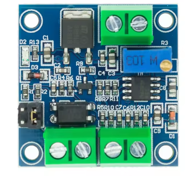
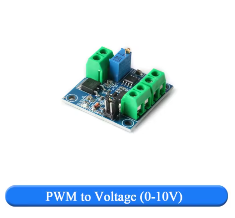
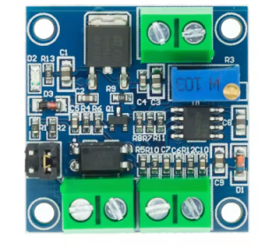
The PWM to Voltage Converter Module is an essential signal interface device designed to bridge the gap between digital microcontrollers and analog industrial equipment. This module converts a Pulse Width Modulation (PWM) signal into a proportional, linear 0-10V DC analog voltage, allowing you to control a vast array of industrial devices using simple digital outputs .
Many modern controllers like Arduino, Raspberry Pi, and various MCUs excel at generating PWM signals but cannot directly output a true 0-10V analog signal. This module solves that problem. By accepting a PWM input (0-100% duty cycle) from your controller, it outputs a clean, adjustable 0-10V voltage that can be used to interface with equipment expecting an analog control signal .
This converter is the perfect tool for integrating low-cost microcontrollers into industrial environments. Its primary applications include:
-
Controlling the speed of industrial motors and pumps via Variable Frequency Drives (VFDs) .
-
Precise dimming of 0-10V dimmable LED drivers and lighting systems .
-
Interfacing with PLC (Programmable Logic Controller) analog input modules .
-
Controlling valve actuators, dampers, and other industrial automation equipment.
-
Providing a stable, adjustable voltage source for testing and laboratory applications.
With its wide input voltage range, selectable logic levels, and onboard calibration, this module provides a professional and reliable solution for translating digital control signals into the analog language of industry .
Key Features
-
Digital to Analog Conversion: Converts a 0%-100% duty cycle PWM digital signal into a linear 0-10V DC analog voltage, with a typical allowable error of less than 5% .
-
Wide Power Supply Range: Operates on a DC supply voltage of 12V to 30V, making it easy to power from existing industrial power rails or a separate 24V supply .
-
Dual Input Logic Level Selection: Features a selectable jumper to match the voltage level of your input PWM signal :
-
5V Position: For PWM signals from 5V microcontrollers (Arduino) and industrial control cards.
-
24V Position: For PWM signals from 12V-24V industrial PLCs and controllers.
-
-
Onboard Calibration Potentiometer: Includes a precision trimmer potentiometer that allows you to calibrate the module. By inputting a 50% duty cycle signal, you can adjust the pot to achieve a precise 5.00V output, ensuring accuracy in your specific setup .
-
High-Quality Signal Conditioning: Employs embedded MCU technology and an operational amplifier (such as the LM358) for stable and reliable conversion, smoothing the PWM signal into a clean DC voltage .
-
Opto-Isolation (Model Dependent): Many versions of this module include an optocoupler (like the PC817) to provide electrical isolation between the input signal and the output circuit, protecting your sensitive controller from electrical noise .
-
Compact and Easy-to-Mount Design: Its small PCB footprint (approx. 33mm x 33mm) is ideal for mounting in control panels or enclosures without taking up valuable space .
-
Clear Screw Terminal Connections: Features labeled screw terminals for secure and reliable connections to power, input signal, and output voltage.
Technical Specifications
| Parameter | Operating Value |
|---|---|
| Operating Voltage (VCC) | 12V – 30V DC |
| Input PWM Signal Frequency | 1kHz – 3kHz (Recommended) |
| Input PWM Signal Level (Selectable) | 5V (4.5V-10V) or 24V (12V-24V) |
| Input Duty Cycle Range | 0% – 100% |
| Output Analog Voltage | 0V – 10V DC |
| Conversion Accuracy | 5% (Typical) |
| Output Drive Current | 10 mA (Max) |
| Module Dimensions | Approx. 33mm x 33mm |
Reviews
There are no reviews yet.