STC8G1K08 core board TSSOP20 development board demo board learning board STC8

SKU: FA1048
Microcontroller Unit (MCU)

STC8G1K08 (Enhanced 8051 Architecture)

Core Speed

Internal Oscillator, up to 35 MHz (approx. 420 MHz equivalent to traditional 8051)

Operating Voltage

2.4V to 5.5V DC

Flash Memory

8KB In-System Programmable FLASH (ISP/IAP)

SRAM

1280 Bytes (1.25 KB)

EEPROM

Integrated EEPROM space

GPIO Pins

Up to 18 usable pins (TSSOP20 package breakout)

Communication Interfaces

1x Hardware UART (TTL Serial), SPI, I2C

Analog Peripherals

8-Channel, 10-bit ADC

Programming Interface

ISP via UART (requires a USB-to-TTL converter)

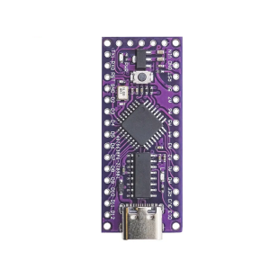
STC8G1K08 Core Board (TSSOP20): High-Speed, Low-Cost 8051 Development Platform 
The STC8G1K08 Core Board is a compact development and learning platform built around the STC8G1K08 microcontroller, a powerful 8-bit MCU based on an enhanced 8051 instruction set architecture. This chip represents a significant leap from traditional 8051 MCUs, operating 12 times faster by executing instructions in just one to three clock cycles. 
Presented in a breadboard-friendly breakout format for its TSSOP20 package, this board offers a highly cost-effective solution for engineers, hobbyists, and students seeking powerful performance for general-purpose embedded applications. Key features include In-System Programming (ISP) via a simple serial interface, multiple timers, a built-in ADC, and low power consumption modes, making it versatile for both simple control tasks and battery-operated projects. 

Key Features
  • Enhanced 8051 Core: High-speed processing performance, typically 12x faster than a conventional 8051 running at the same clock frequency.
  • Integrated ISP Programming: Allows code download directly via UART (TTL serial port), eliminating the need for expensive dedicated programmers.
  • Rich On-Chip Peripherals: Includes integrated 10-bit ADC (Analog-to-Digital Converter), multiple timers, hardware UART, SPI, and I2C support.
  • Compact Form Factor: Breadboard-compatible design with all relevant GPIO pins broken out for easy prototyping.
  • Low Power Consumption: Features flexible clock modes and power-down states suitable for energy-efficient or battery-powered devices.
  • Wide Voltage Range: Operates over a flexible 2.4V to 5.5V supply voltage range, making it adaptable to both 3.3V and 5V systems. 

Technical Parameters (Specifications)
Parameter  Value/Description
Microcontroller Unit (MCU) STC8G1K08 (Enhanced 8051 Architecture)
Core Speed Internal Oscillator, up to 35 MHz (approx. 420 MHz equivalent to traditional 8051)
Operating Voltage 2.4V to 5.5V DC
Flash Memory 8KB In-System Programmable FLASH (ISP/IAP)
SRAM 1280 Bytes (1.25 KB)
EEPROM Integrated EEPROM space
GPIO Pins Up to 18 usable pins (TSSOP20 package breakout)
Communication Interfaces 1x Hardware UART (TTL Serial), SPI, I2C
Analog Peripherals 8-Channel, 10-bit ADC
Programming Interface ISP via UART (requires a USB-to-TTL converter)

Usage Instructions
This development board requires specific software tools for programming and configuration. 
Step-by-Step Integration:
  1. Software Setup: Download the official STC-ISP programming utility (often runs on Windows via Wine on Linux/Mac) and install a C51 compiler environment like Keil uVision.
  2. Hardware Connection: Connect the core board to your PC using a USB-to-TTL Serial Adapter (e.g., FTDI or CH340), linking the module’s RXD to the adapter’s TXD, TXD to RXD, and GND to GND.
  3. Programming Sequence:
    • In the STC-ISP software, select the correct MCU model (STC8G1K08) and your PC’s COM port.
    • Load the compiled .hex firmware file.
    • Click “Download” in the software.
    • Power Cycle the Board: Unplug and immediately re-plug the board’s power (or press the reset button if one is present on the board version) to initiate the flash download sequence. The chip enters ISP mode upon power-up.
  4. Development: Use the broken-out GPIO pins with a breadboard to connect sensors, displays, and other peripherals using standard jumper wires.
Q: What software do I use to write code for the STC8G1K08?

The most common environment is the Keil C51 compiler suite for C programming, combined with the free STC-ISP software for flashing the compiled .hex file.

Q: Do I need a special hardware programmer device?

No, a standard and inexpensive USB-to-TTL serial adapter is sufficient. The chip programs itself in-system via the serial port.

Q: Is this board compatible with the Arduino IDE?

The STC8 series uses the 8051 instruction set and is not natively compatible with the Arduino IDE or ecosystem. It requires traditional C programming methods.

Q: I am a business buyer. Is this chip reliable for commercial production?

Yes, the STC8 series is widely used in high-volume commercial embedded applications in Asia due to its robust performance, low cost, and reliability. The core board is intended for rapid prototyping before moving to custom PCB production.

Q: What is the input voltage range for this specific core board?

The board can operate within the wide range of 2.4V to 5.5V DC, allowing it to work with both standard 3.3V and 5V power systems.