Pure sine wave inverter driver board EGS002 “EG8010+IR2110”

SKU: FA2175
Chipset

EG8010 (ASIC) + 2× IR2110S (MOSFET Drivers) + LM393 (Comparator)

Supply Voltage (EG8010)

5V DC

Supply Voltage (IR2110S)

12V – 15V DC

PWM Carrier Frequency

23.4 kHz

Crystal Oscillator

12MHz external

Output Frequencies

50Hz fixed / 60Hz fixed / 0-100Hz adjustable / 0-400Hz adjustable (jumper selectable)

Dead Time Options

300ns / 500ns / 1.0μs / 1.5μs (jumper selectable)

Soft Start Time

3 seconds (jumper selectable)

Modulation Modes

Unipolar SPWM (default) / Bipolar SPWM

Protection Features

Over-voltage, under-voltage, over-current, over-temperature

Description

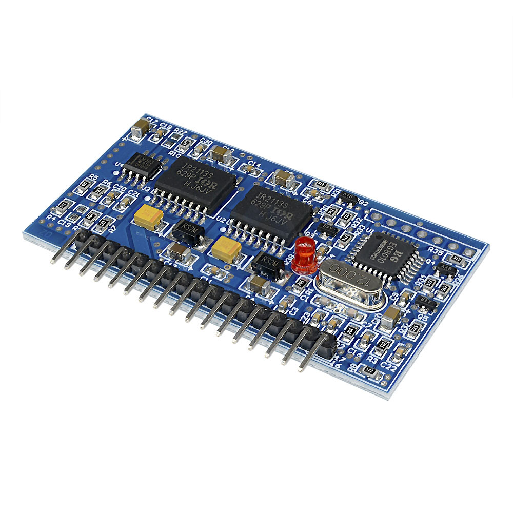
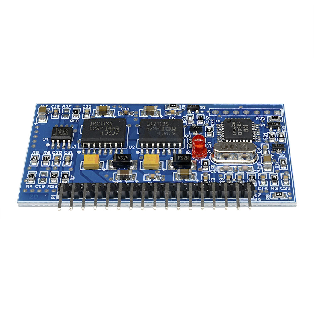
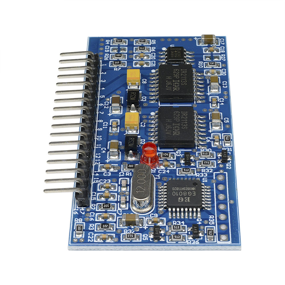
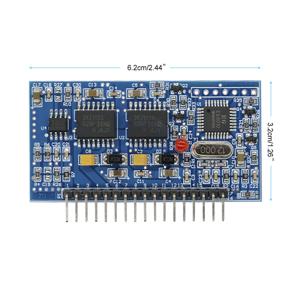
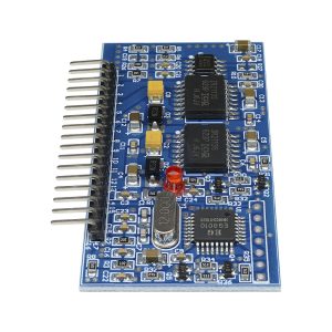
The EGS002 is a high-performance, intelligent SPWM (Sinusoidal Pulse Width Modulation) driver board specifically designed for single-phase pure sine wave inverters. It combines the EG8010 pure sine wave ASIC (Application Specific Integrated Circuit) with the robust IR2110S high and low-side MOSFET driver ICs, providing a complete, ready-to-use solution for building professional-grade DC-AC power inverters .

Unlike modified square wave inverters that can cause humming in motors and are unsuitable for sensitive electronics, the EGS002 generates a true pure sine wave output with low harmonic distortion. This makes it safe to power laptops, computers, smartphones, medical devices, and inductive loads like fans and pumps .

The EG8010 chip integrates all the critical functions required for a modern inverter: a precise SPWM generator, dead-time control circuit, soft-start mechanism, and comprehensive protection features including over-voltage, under-voltage, over-current, and over-temperature protection . An external 12MHz crystal oscillator ensures high frequency accuracy and waveform stability.

The board features two IR2110S driver ICs configured to drive two separate MOSFET half-bridges, along with cross-conduction prevention logic for enhanced anti-interference capability . A voltage comparator (LM393) provides over-current protection feedback.

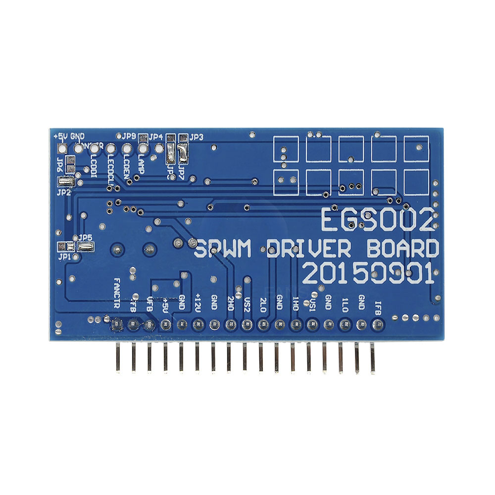
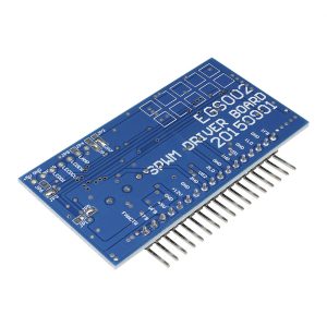
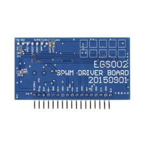
Housed on a compact 62mm × 33mm PCB, the EGS002 provides jumper-selectable configuration for output frequency (50/60Hz), dead time (300ns, 500ns, 1.0μs, 1.5μs), and soft-start enable/disable, eliminating the need for programming or external microcontrollers . An optional 128×32 serial LCD interface allows real-time monitoring of output voltage, frequency, temperature, and current .

Whether you are building a solar power system, a UPS backup, a wind power inverter, or a motor speed controller, the EGS002 driver board provides the intelligence and reliability required for both hobbyist and professional applications.

Key Features

  • Pure Sine Wave Output – Generates true sine wave AC with low harmonic distortion, safe for sensitive electronics and inductive loads 

  • Integrated EG8010 ASIC – CMOS technology IC integrates SPWM generator, dead-time control, soft start, protection circuits, RS232 serial communication, and LCD driver module 

  • IR2110S MOSFET Drivers – Two high-performance high/low-side driver ICs for driving two MOSFET half-bridges; supports bootstrap operation for high-side switching 

  • Dual Modulation Modes – Supports both unipolar and bipolar SPWM modulation (default unipolar) 

  • Adjustable Output Frequency – Jumper selectable: 50Hz fixed, 60Hz fixed, 0-100Hz adjustable, or 0-400Hz adjustable 

  • Configurable Dead Time – Four dead time options via jumpers: 300ns, 500ns, 1.0μs, or 1.5μs 

  • Soft Start Function – Jumper-enableable 3-second soft start to reduce inrush current during startup 

  • Comprehensive Protection – Over-voltage protection (OVP), under-voltage protection (UVP), over-current protection (OCP), and over-temperature protection (OTP) 

  • LED Fault Indication – 3mm red LED indicates fault conditions with distinct blink patterns for each protection type 

  • External 12MHz Crystal Oscillator – Provides high precision timing and low harmonic distortion 

  • Real-Time Feedback – Monitors voltage, current, and temperature for closed-loop control 

  • Serial Communication & LCD Support – RS232 interface for parameter configuration (voltage, frequency, etc.) and 128×32 serial LCD display support for real-time monitoring 

  • No Programming Required – All parameters are set via hardware jumpers; no firmware coding needed 

  • Compact Size – 62mm × 33mm PCB, suitable for integration into various inverter designs

Technical Specifications 

Specification Value
Chipset EG8010 (ASIC) + 2× IR2110S (MOSFET Drivers) + LM393 (Comparator) 
Supply Voltage (EG8010) 5V DC 
Supply Voltage (IR2110S) 12V – 15V DC 
PWM Carrier Frequency 23.4 kHz 
Crystal Oscillator 12MHz external 
Output Frequencies 50Hz fixed / 60Hz fixed / 0-100Hz adjustable / 0-400Hz adjustable (jumper selectable) 
Dead Time Options 300ns / 500ns / 1.0μs / 1.5μs (jumper selectable) 
Soft Start Time 3 seconds (jumper selectable) 
Modulation Modes Unipolar SPWM (default) / Bipolar SPWM 
Protection Features Over-voltage, under-voltage, over-current, over-temperature 
LCD Interface 128×32 serial LCD (optional) 
Operating Temperature -20°C to +50°C 
Board Dimensions 62mm × 33mm × approx. 20mm 
Mounting 2× 3mm mounting holes 

Typical Usage

  • Solar Power Inverters – Convert DC from solar panels or batteries to AC for home appliances 

  • Uninterruptible Power Supply (UPS) Systems – Provide backup power during grid outages 

  • Wind Power Inverters – Convert variable DC from wind turbines to stable AC 

  • Digital Generator Systems – Portable inverter generators with pure sine wave output 

  • Single-Phase Motor Speed Controllers – Variable frequency drives for AC motors 

  • Car/Vehicle Power Inverters – 12V DC to 110V/220V AC for powering laptops, chargers, and small appliances 

  • Camping & Outdoor Power Supplies – Portable power stations 

  • Sine Wave Dimmers & Regulators – Precision AC voltage control 

  • IF Power Applications – Induction heating and other intermediate frequency applications 

  • Home Appliance Power Supply – TV, computer, DVD, VCD, satellite receiver, printer, fluorescent lamps, stereos, fans, lighting 

Q: What is the difference between a pure sine wave inverter and a modified sine wave inverter?

A pure sine wave inverter (like what this board helps build) produces AC power that is identical or cleaner than the grid power. Modified square wave inverters produce stepped waveforms that contain harmonics. Pure sine wave is required for sensitive electronics (laptops, medical devices, variable speed tools, laser printers) and prevents humming noise in motors and transformers .

Q: Do I need to program this board? Does it require a microcontroller?

No. The EGS002 is a hardware-configurable board. All settings (frequency, dead time, soft start, modulation mode) are selected using onboard jumpers (JP1 to JP9). No programming, coding, or external microcontroller is required .

Q: What power supply voltages does this board need?

The board requires two separate DC power supplies: 5V DC for the EG8010 control logic, and 12V-15V DC for the IR2110S MOSFET drivers . Do not power the board from a single voltage source without proper voltage regulation.

Q: Can this board directly drive IGBTs?

The IR2110S drivers on this board are designed for MOSFETs. If you intend to use IGBTs, ensure the gate drive voltage is sufficient (typically 15V minimum for IGBTs). Some users have reported issues with IGBTs not fully turning on with standard 12V driver supplies, leading to overheating . For IGBT applications, verify the gate drive requirements of your specific IGBTs.

Q: How do I set the output frequency to 50Hz or 60Hz?
  • 50Hz: Short jumper JP5 

  • 60Hz: Short jumper JP1 
    Only one frequency jumper should be shorted at a time.

Q: How do I set the dead time?

The dead time is set by shorting specific jumper combinations :

Dead Time Jumpers to Short
300ns JP7 + JP8
500ns JP3 + JP8
1.0μs JP4 + JP7
1.5μs JP3 + JP4
Q: How do I enable or disable soft start?
  • Enable Soft Start (3 seconds): Short jumper JP2 

  • Disable Soft Start: Short jumper JP6 

Q: What does the red LED indicate?

The 3mm red LED provides fault indication with specific blink patterns :

Condition LED Behavior
Normal Operation Always ON
Over-Current (OCP) Blinks twice, off 2 seconds, repeats
Over-Voltage (OVP) Blinks three times, off 2 seconds, repeats
Under-Voltage (UVP) Blinks four times, off 2 seconds, repeats
Over-Temperature (OTP) Blinks five times, off 2 seconds, repeats
Q: What is the difference between unipolar and bipolar SPWM modulation?

Unipolar SPWM (default mode) switches the output between 0 and +Vdc (or 0 and -Vdc) in each half-cycle. It offers lower harmonic distortion and simpler filtering. Bipolar SPWM switches between +Vdc and -Vdc, which can be more efficient for some designs. The default mode is unipolar; to use bipolar, connect the MODSEL pin (pin 20 on EG8010) to GND .

Q: Can I monitor the inverter's performance in real-time?

Yes. The EGS002 has an interface for a 128×32 serial LCD module (optional, not included) that displays output voltage, frequency, temperature, and current. It also supports RS232 serial communication for computer-based monitoring and parameter configuration .