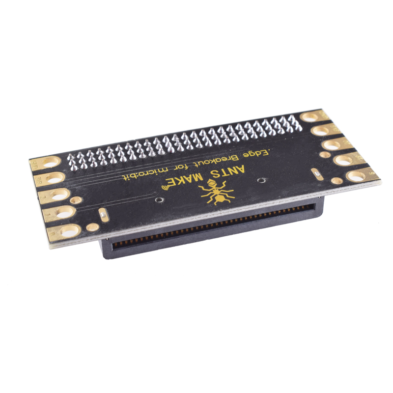

The AM-001 micro:bit Expansion Shield is a high-performance breakout board designed to maximize the potential of the BBC micro:bit for students, makers, and professional engineers. It simplifies the connection of multiple peripherals by breaking out all of the micro:bit’s proprietary edge connector pins into standard, accessible interfaces.
Long Description
The AM-001 micro:bit Expansion Shield is a versatile I/O breakout board compatible with both micro:bit V1 and V2. Designed for seamless integration, it allows users to connect a vast range of sensors, actuators, and communication modules without the need for complex wiring or crocodile clips.
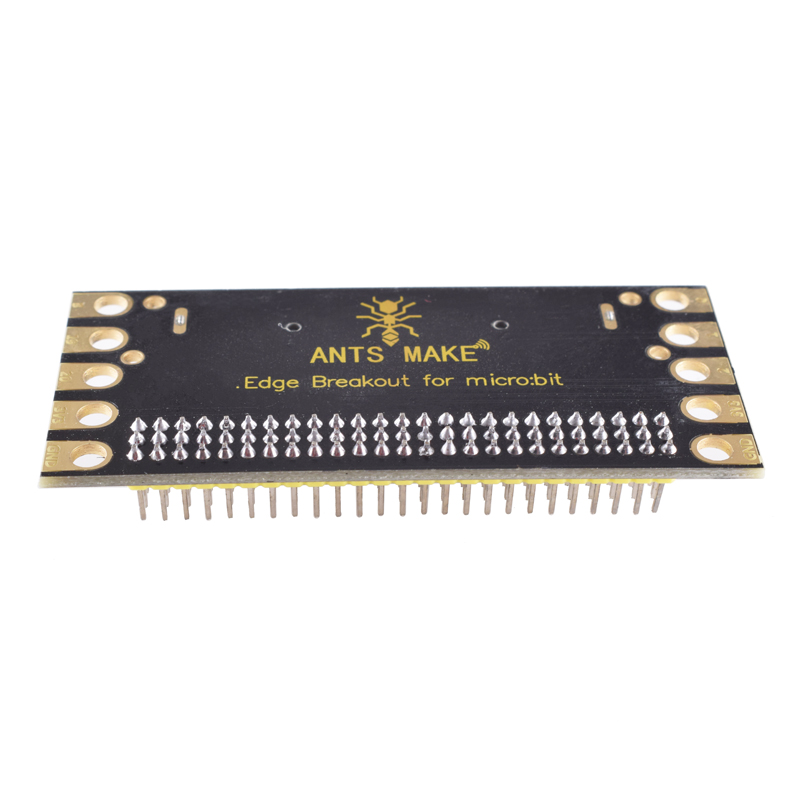
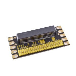
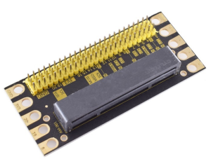
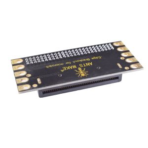
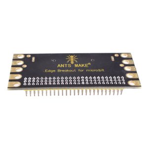
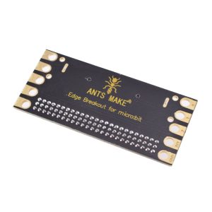
The board features a direct-insertion slot for the micro:bit and expands all available GPIO pins into a standard G-V-S (Ground-Voltage-Signal) 3-pin header format. Each header is color-coded (Black for GND, Red for 3.3V, and Yellow for Signal) to prevent wiring errors and ensure safety during prototyping. With an integrated voltage regulator and a dedicated DC power jack, it provides a stable 3.3V power supply, making it capable of running complex projects that require more current than the micro:bit can provide on its own.
Key Features
- Plug-and-Play Design: Features a user-friendly 40-pin horizontal socket for the micro:bit; no tools or soldering required.
- Comprehensive Breakout: Provides easy access to all digital and analog pins (P0-P2, P8, P12-P16, P19-P20).
- Advanced Communication: Includes dedicated interfaces for I2C and SPI protocols, perfect for OLED displays and high-end sensors.
- Built-in Passive Buzzer: Features an onboard buzzer connected to pin P0 for immediate audio feedback.
- Independent Jumper Control: A jumper cap allows you to disconnect the buzzer from P0, releasing the pin for other general-purpose I/O tasks.
- LEGO Compatibility: Includes standard mounting holes (approx. 4.8mm diameter) compatible with building block friction pins for structural projects.